Panasonic AWHB605 AWHB605 User Guide - Page 9
Operations, System Connections
 |
View all Panasonic AWHB605 manuals
Add to My Manuals
Save this manual to your list of manuals |
Page 9 highlights
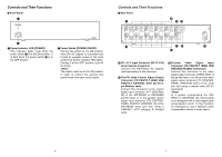
System Connections (Indoor Pan/tilt Head System) $ Example System Setup Zoom/focus control Iris control Color monitor (75 Ω terminator) Adjustment such as cable compensation, genlock adjustment, and total pedestal adjustment should be applied to the video signals output from the AW-HB505. Convertible camera Video S-Video Servo control zoom lens Camera cable: AW-CA50T15 Pan/tilt head control Camera control Option switch control: Unnecessary if no optional unit is connected. Lamp control: Unnecessary if no halogen lamp is used. Gen-lock Video DC15V Halogen lamp POWER OFF ON Contact Pan/tilt head AC adapter: AW-PS300 Optional unit Multi port hub: AW-HB505 POWER OFF ON 1 Y C 2 Y C CABLE COMP 3 Y C 4 Y C 5 Y C Multl Port Hub AW-H8505 AC adapter: AW-PS505 O I Preview Video Gen-lock Camera control Multi control hub: AW-HB605 Pan/tilt head control O I AC adapter: AW-PS505 Preview color monitor Preview Video (75 Ω terminator) Multi hybrid control panel: AW-RP505 Priority switchbox AC adapter: AW-PS301 Camera control Pan/tilt head control Preview Video 16 Operations 1. Turn the power on. Turn on the power control switches of the AC adapters of the pan/tilt heads and control panels, as well as the AC adapter and power control switch of the multi control hub. If the system incorporates a multi port hub, turn on the power control switch of the multi port hub and the power switch of its AC adapter. 2. Press the button on the priority switchbox connected to the control panel you wish to operate. This activates the connected control panel. If the system incorporates a multi hybrid control panel, use the camera and pan/tilt head selector switch on the multi hybrid control panel to select a pan/tilt head. (The control panel is activated once its memory switch stops flashing and goes dark.) O Immediately after the power is turned on the system is in a status in which no control panel is selected. After turning the power on, do not fail to press the priority switchbox connected to the control panel you wish to operate. After this operation is performed the power supply to the camera and pan/tilt head turns on. O The active control panel is always the one connected to the priority switchbox pressed last. 3. Perform the mounting balance adjustment on the cameras. For detailed instructions, refer to the manuals accompanying the relevant equipment. 4. Set the limits to the range of movement for the pan/tilt head (limiter). For detailed instructions, refer to the manuals accompanying the relevant equipment. 5. If the system incorporates a hybrid control panel or multi hybrid control panel, perform video signal cable compensation, G/L (gen-lock) adjustment, and total pedestal adjustment. Also set the switches as appropriate. For detailed instructions, refer to the manuals accompanying the relevant equipment. After performing G/L (gen-lock) adjustment and total pedestal adjustment, set the control panel's G/L phase adjustment switch to the OFF position. The instruction manual of the hybrid control panel states that this switch should be left in the ON position, but it should be set to OFF on systems using the multi control hub. 6. Store the preset settings for the cameras and pan/tilt heads in memory (systems incorporating hybrid control panel or multi hybrid control panel only). For detailed instructions, refer to the manuals accompanying the relevant equipment. The preset settings are stored in the memory of the pan/tilt head. When new preset settings are stored in memory, all the previous settings (including those stored in memory using the control panel) are overwritten. The adjustments and settings described 3 6 in steps though above may be omitted if no changes need to be made to the current adjustments and settings. 17
-
 1
1 -
2
-
3
-
 4
4 -
 5
5 -
 6
6 -
 7
7 -
 8
8 -
 9
9 -
 10
10 -
 11
11
 |
 |
