Panasonic BB-HCM715A Installation Guide - Page 3
Mounting the Camera - bb hcm715
 |
UPC - 037988845606
View all Panasonic BB-HCM715A manuals
Add to My Manuals
Save this manual to your list of manuals |
Page 3 highlights
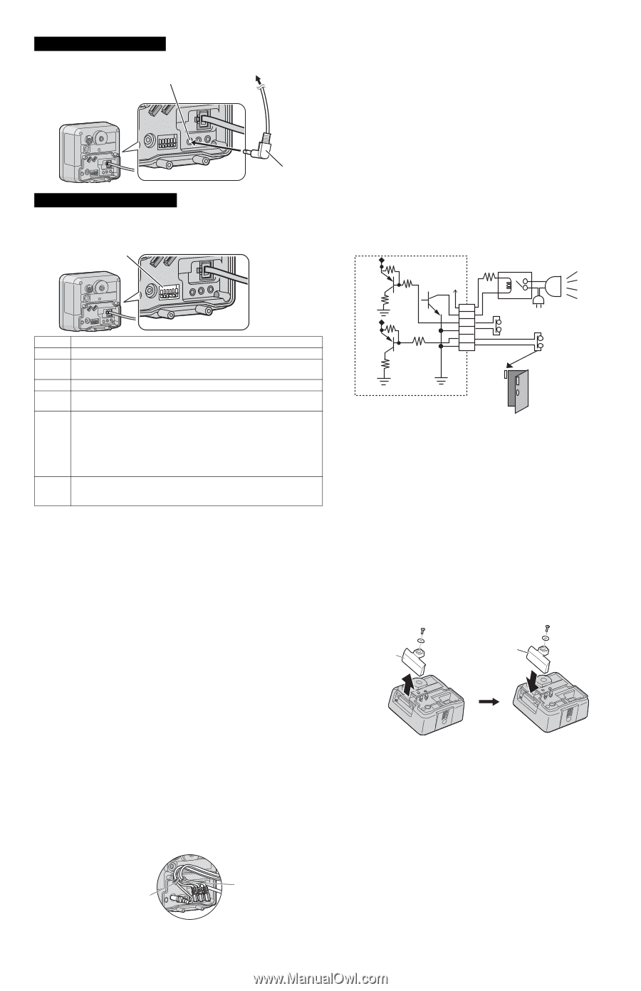
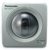
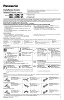
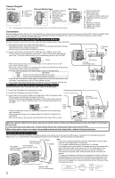
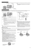
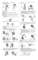
Connecting a Video Device You can connect a TV or other video device (NTSC or PAL format) to the camera to monitor or record camera images. Connect the video device as shown below. For video device To video device Note • Analog video output is disabled by default. See 7.5 Controlling the Analog Video Output Signal in the Operating Instructions on the CD-ROM for more information. Video cable (φ 3.5 mm plug) Connecting External Sensors The camera's external I/O interface allows you to connect 2 devices (such as sensors, motion detectors, etc.) that can be used to trigger the camera's image buffering and transferring features (see Section 2 Using Triggers to Buffer and Transfer Images in the Operating Instructions on the CD-ROM). The external I/O interface has 6 terminals. External I/O interface Circuit Diagram Example Camera Relay Light 12 V* Terminal G GND terminal. Description 4 3 Door Sensor 2 (Alarm 2) 2 G Door Sensor 1 (Alarm 1) 1 G 1 External sensor input 1. The camera can be triggered by either an open circuit or a GND short-circuit. G GND terminal. 2 External sensor input 2. The camera can be triggered by either an open circuit or a GND short-circuit. *DC 10.5 V-13 V External device control output. Allows you to control an external device using the output buttons in the camera's operation bar (for example, turning a light on or off). 3 • This terminal's behavior can be changed (see 7.4 Controlling the External Output Terminal in the Operating Instructions on the CD-ROM). • This terminal is an open collector circuit. The maximum drawing current is the same as terminal 4. Do not exceed the voltage of the terminal 4. DC power output terminal. 4 • 10.5-13 V DC • Maximum load drive is 100 mA. Note • Do not push strongly on the external I/O interface with the pointed object. The external I/O interface may get stuck into the unit, and you may not be able to use it. Caution • The external I/O interface is not capable of connecting directly to devices that require large amounts of current. In some cases, a custom interface circuit (customer-provided) may have to be used. Serious damage to the camera may result if a device that exceeds its electrical capability is connected to the external I/O interface. • Low voltage/current circuits and high voltage/current circuits are used in the camera circuit. All wiring should be performed by a qualified electrician. Incorrect wiring could damage the camera and cause a fatal electric shock. • External devices connected to the camera's output terminals cannot be controlled in the event of a network error or failure. Keep this in mind when connecting door locks, heat-emitting devices, or other devices that may be dangerous if they cannot be controlled. Mounting the Camera Three mounting methods are available, as shown here. Confirm which side is the top and bottom of the camera when mounting; do not mount the camera upside down. Consult an authorized dealer for mounting. Caution • Do not drive the screws into a soft material. Drive the screws into a secure area of the wall or ceiling, such as a column, otherwise the camera may fall and be damaged. • Make sure you attach the safety wire when mounting the camera, to prevent the camera from falling. Note • For BB-HCM715: The camera is intended for indoor use only and should not be mounted outdoors. • For BB-HCM735: If you install the camera outdoors, the external microphone or speaker must be outdoor compatible. • Use screws that are appropriate for the material of the wall or ceiling. • The included screws are for use with wooden walls or ceilings only. • To ensure that camera images are displayed properly, do not mount the camera on an incline. Mount the camera so that it is perpendicular to the floor. Do not mount the camera upside down. • Mounting and cabling instructions described in this document follow generally accepted guidelines suitable for residential installations. In some areas, commercial and industrial installations are regulated by local or state ordinances. For such installations, contact your local building department or building inspector for more details. • Camera images can be viewed in relatively dark areas, however, image quality decreases when viewing dark images. We recommend using supplemental lighting for best results. • Prolonged exposure to direct sunlight or halogen light may damage the camera's image sensor. Mount the camera appropriately. • When mounting the camera, make sure to wrap the AC adaptor cord (if used) and other cables (external microphone or speaker cable, video cable, etc.) around the hooks as shown to ensure secure connections. • For BB-HCM715: To suit the area in which you will install the camera, you can attach the provided SD Card Cover (Hard type), in order to help prevent SD card theft. (Not all forms of theft can be prevented.) SD Card Cover (Soft type) SD Card Cover (Hard type) Hook for AC adaptor cord, video cable, external I/O interface wires Hook for external audio cables 3
-
 1
1 -
 2
2 -
 3
3 -
 4
4
 |
 |