Panasonic BL-C101A Installation Guide - Page 2
Camera Diagrams, Connections, BL-C101, BL-C121 - network camera
 |
UPC - 037988845491
View all Panasonic BL-C101A manuals
Add to My Manuals
Save this manual to your list of manuals |
Page 2 highlights
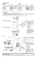
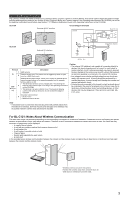
Camera Diagrams BL-C101 Front View Rear View A Indicator*1 B Lens D A C Microphone B C BL-C121 Front View D FACTORY DEFAULT RESET button E Serial number label E F Stand/Tripod Mounting Hole F G External INPUT interface G H DATA/POWER IN H Rear View A Indicator*1 B Lens C Microphone A D B E F C *1 See 1.1 Understanding the Camera Indicator in the Troubleshooting Guide on the CD-ROM for indicator meaning. D FACTORY DEFAULT RESET button E WIRELESS/WIRED G switch F LAN port H G Serial number label I H Stand/Tripod Mounting Hole J I External I/O interface K J DC IN jack K Hook for AC adaptor cord Connections Connect the camera to your router and to the power outlet as described below. • Before proceeding, confirm that your PC is connected to your router and can access the Internet. Also confirm that your router's UPnP™ feature is enabled. (Most routers have UPnP™ turned off by default.) Refer to the operating instructions included with your router or to the Panasonic Network Camera website (http://panasonic.net/pcc/support/netwkcam/) for more information. BL-C101 • Use a LAN cable that is no more than 30 m (98 feet 5 inches) long to connect the camera and the power transfer unit. 1 Connect the LAN cable to the camera and the power transfer unit. LAN cable (Cat-5 straight cable) Power transfer unit 2 Connect the LAN cable to the router and the power transfer unit. LAN cable Router Modem 3 Connect the AC adaptor to the power transfer unit and plug the AC adaptor into the power outlet. To the power • Confirm that the indicator turns green after about 1 minute. If it does outlet not turn green, see 1.2 Camera (For BL- Indicator Issues in the C101CE/ Troubleshooting Guide on the CD- BL-C101E ROM. use an AC cord) Green AC adaptor • When you operate the camera, the power outlet should be near the camera and easily accessible. • Use only specified Panasonic AC adaptor (Order No. PQLV206Y for BL-C101A, PQLV216CE1Z for BLC101CE, BL-C101E). • The camera may become warm. This is normal. BL-C121 Internet PC 1 Confirm that the WIRELESS/WIRED switch on the side of the camera is set to WIRED. 2 Connect the LAN cable to the camera and the router. WIRELESS/WIRED switch 3 Connect the AC adaptor cord to the DC IN jack. 4 Plug the AC adaptor into the power outlet. • Confirm that the indicator turns green after about 1 minute. If it does not turn green, see 1.2 Camera Indicator Issues in the Troubleshooting Guide on the CDROM. Router WAN LAN 4321 Internet Modem LAN cable (Cat-5 straight cable) PC To the power Green outlet (For BL- C121CE/BL- C121E use an • When you operate the camera, the power AC cord) outlet should be near the camera and easily accessible. • Use only specified Panasonic AC adaptor AC adaptor (Order No. PQLV206Y for BL-C121A, PQLV216CE1Z for BL-C121CE, BL- C121E). • The camera may become warm. This is normal. After the camera's indicator turns green, you may set up the camera. Continue by following the procedure described in the included Setup Guide. • If the indicator does not turn green, see 1.2 Camera Indicator Issues in the Troubleshooting Guide on the included CD-ROM. 2
-
 1
1 -
 2
2 -
 3
3 -
 4
4
 |
 |
