Panasonic BL-C111A Installation Guide - Page 2
Camera Diagrams, BL-C111, BL-C131, Connections - setup guide
 |
UPC - 037988845149
View all Panasonic BL-C111A manuals
Add to My Manuals
Save this manual to your list of manuals |
Page 2 highlights
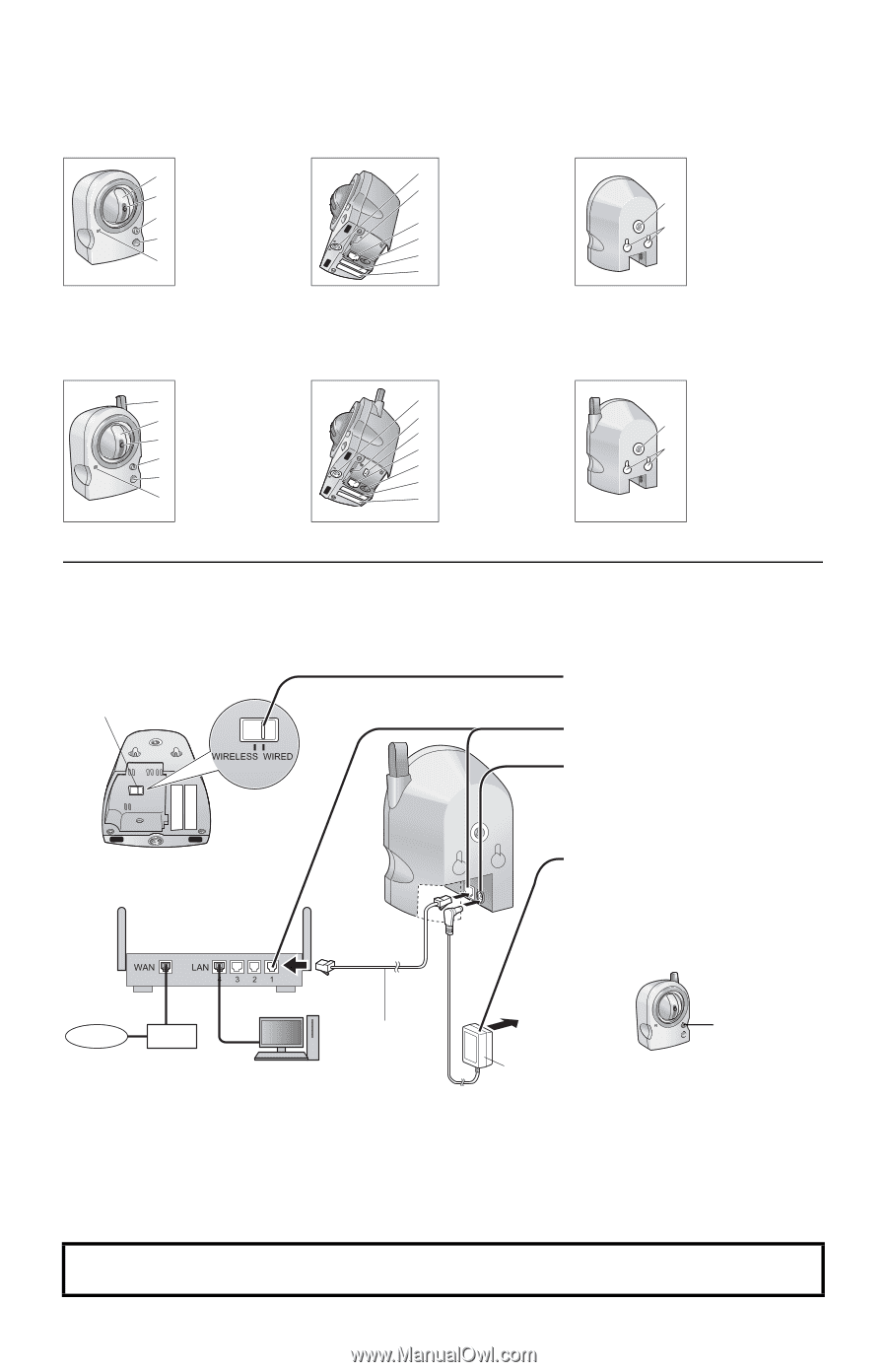
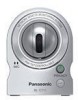
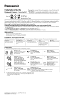
Camera Diagrams BL-C111 Front View Bottom View Rear View A Lens housing A (pan/tilt mechanism) B B Lens C Indicator*1/ C PRIVACY button*2 D D Built-in sensor (pyroelectric infrared E sensor) E Microphone F Tripod mounting hole F G FACTORY DEFAULT G RESET button H LAN port H I DC IN jack I J MAC address label K Serial number label J K *1 See 1.1 Understanding the Camera Indicator in the Troubleshooting Guide on the CD-ROM for indicator meaning. *2 See "PRIVACY Button" on page 4 for information about the PRIVACY button. L Tripod mounting hole M Wall mounting holes L M BL-C131 Front View Bottom View A Antenna A B Lens housing B (pan/tilt mechanism) C Lens C D Indicator*1/ D PRIVACY button*2 E Built-in sensor E (pyroelectric infrared F sensor) F Microphone Rear View G Tripod mounting hole G H FACTORY DEFAULT H RESET button I I WIRELESS/WIRED J switch J LAN port K K DC IN jack L L MAC address label M M Serial number label *1 See 1.1 Understanding the Camera Indicator in the Troubleshooting Guide on the CD-ROM for indicator meaning. *2 See "PRIVACY Button" on page 4 for information about the PRIVACY button. N Tripod mounting hole O Wall mounting holes N O Connections Connect the camera to your router and to the power outlet as described below. • Before proceeding, confirm that your PC is connected to your router and can access the Internet. Also confirm that your router's UPnP™ feature is enabled. (Most routers have UPnP™ turned off by default.) Refer to the operating instructions included with your router or to the Panasonic Network Camera website (http://panasonic.co.jp/pcc/products/en/netwkcam/) for more information. • The camera illustrations in this document depict the BL-C131. WIRELESS/WIRED switch 1 BL-C131 only: Confirm that the WIRELESS/ WIRED switch on the bottom of the camera is set to WIRED. 2 Connect the LAN cable to the camera and the router. 3 Connect the AC adaptor cord to the DC IN jack. Bottom of BL-C131 Router 4 Plug the AC adaptor into the power outlet. • The lens will pan and tilt when the camera is turned on. • Confirm that the indicator lights green after about 1 minute. If the indicator does not light green, see 1.2 Camera Indicator Issues in the Troubleshooting Guide on the CD-ROM. Internet Modem LAN cable (Cat-5 straight cable) PC To the power outlet AC adaptor Green • The AC adaptor is used as the main disconnect device. Ensure that the AC outlet is installed near the product and is easily accessible. • Use only specified Panasonic AC adaptor (BL-C111CE/BL-C131CE: model no. PQLV206CE [order no. PQLV206CEY], BL-C111E/BL-C131E: model no. PQLV206E [order no. PQLV206EY]). • When the lens pans or tilts, a sound can be heard from the camera. This is normal. • The camera may become warm. This is normal. After the camera's indicator turns green, you may set up the camera. Continue by following the procedure described in the included Setup Guide. • If the indicator does not turn green, see 1.2 Camera Indicator Issues in the Troubleshooting Guide on the included CD-ROM. 2
-
 1
1 -
 2
2 -
 3
3 -
 4
4
 |
 |