Panasonic CF52PFNBEPM User Manual - Page 10
Getting Started
 |
View all Panasonic CF52PFNBEPM manuals
Add to My Manuals
Save this manual to your list of manuals |
Page 10 highlights
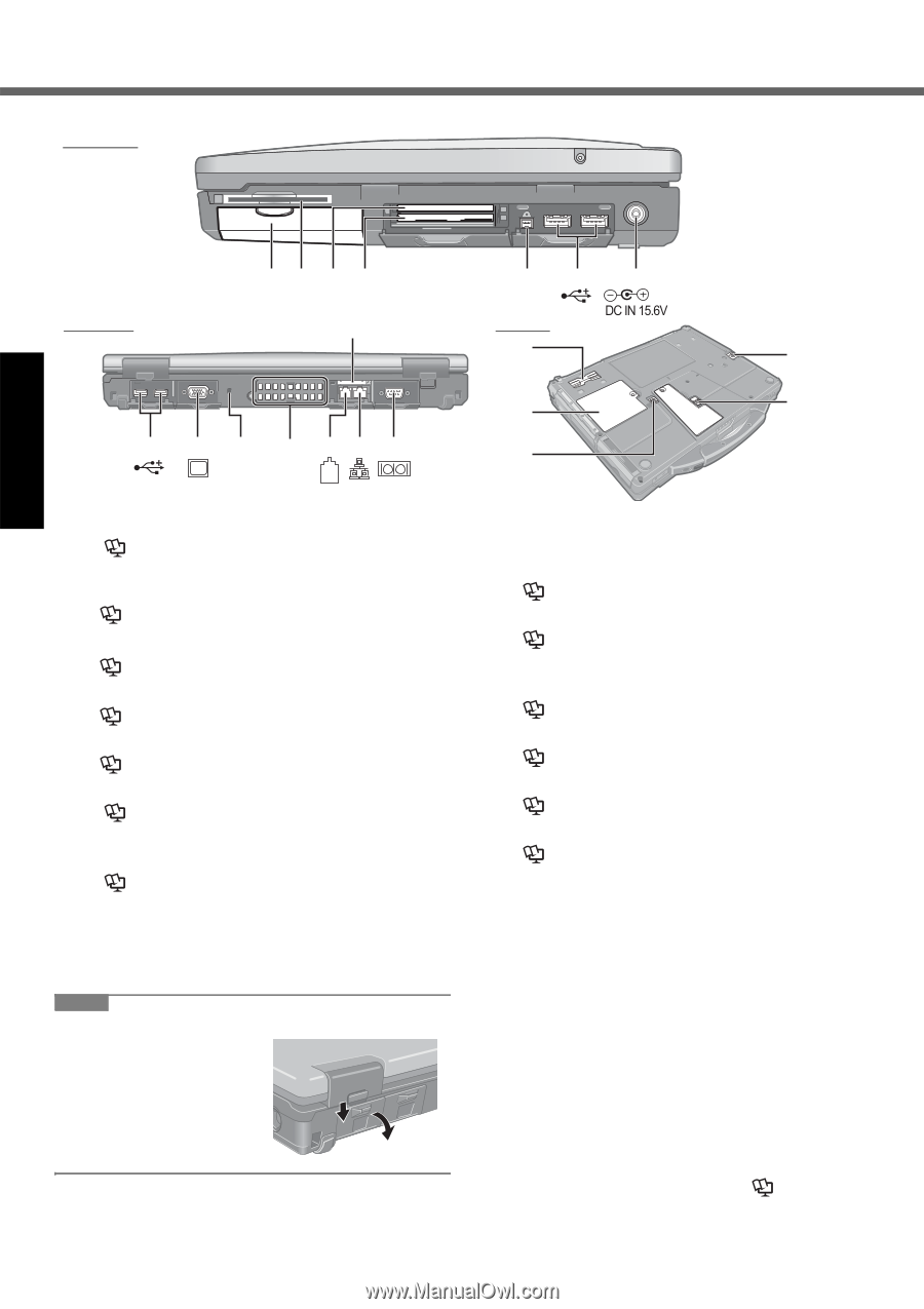
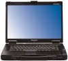
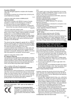
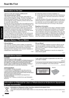
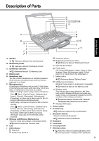
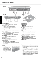
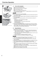
Description of Parts Right side Getting Started AB C D EX PC EF G 1394 Rear side K Bottom O R P S F H I J LM N Q LOCK A : Hard disk drive Reference Manual "Hard Disk Drive" B : Smart Card slot Reference Manual "Smart Card" C : ExpressCard slot*1 Reference Manual "PC Card / ExpressCard" D :PC Card slot *1 Reference Manual "PC Card / ExpressCard" E : IEEE 1394 interface connector Reference Manual "IEEE 1394 Devices" F : USB port Reference Manual "USB Devices" G : DC-IN jack H : External display port Reference Manual "External Display" I : Security lock A Kensington cable can be connected. For further information, read the manual that comes with the cable. J : Ventilation hole K : SIM Card slot L : Modem port Reference Manual "Modem" M : LAN port Reference Manual "LAN" N : Serial port O : Expansion bus connector Reference Manual "Port Replicator" P : RAM module slot Reference Manual "RAM Module" Q : Hard disk drive latch Reference Manual "Hard Disk Drive" R : Multimedia pocket release button Reference Manual "Multimedia Pocket" S : Battery latch NOTE When you open the covers (Example: USB port cover) of ExpressCard slot, PC card slot, IEEE 1394 interface connector, USB port, External display port, Modem port, LAN port and Serial port, push down and pull the covers. *1 Dummy cards are set in the PC Card slot and ExpressCard slot respectively. • Be sure to insert each dummy card when the slots are not in use. • Insert the appropriate dummy card in the correct card slot. Insert the dummy PC Card in the PC Card slot and dummy ExpressCard in the ExpressCard slot. Inserting dummy card in the wrong slot may cause malfunction of the computer. • Insert and remove each dummy card as the same way as PC Card/ExpressCard. ( Reference Manual "PC Card/ExpressCard") 10
-
 1
1 -
2
-
3
-
4
-
 5
5 -
 6
6 -
 7
7 -
 8
8 -
 9
9 -
 10
10 -
 11
11 -
 12
12 -
 13
13 -
 14
14 -
 15
15 -
16
-
17
-
18
-
19
-
20
-
21
-
22
-
23
-
24
-
25
-
26
-
27
-
28
-
29
-
30
-
31
-
32
-
33
-
34
-
35
-
36
-
37
-
38
-
39
-
40
 |
 |