Panasonic EY7960 Service Manual - Page 8
Ref. No. 2C, Procedure, Removal or attachment of the Gear Box Block., EY7460, EY7960
 |
View all Panasonic EY7960 manuals
Add to My Manuals
Save this manual to your list of manuals |
Page 8 highlights
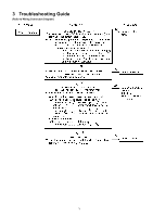
Ref. No. 2C Procedure 2A → 2B → 2C Fig. 8 Fig. 9 Removal or attachment of the Gear Box Block. EY7460 (Removal) 1. Turn the thrust plate to remove. 2. The internal parts of gear box block can be removed one after another. (See Fig. 8) (Attachment) 1. Start from inserting 6 rollers and balls into the holes of driving block one of each as shown in the Fig. 9. 2. Insert 6 pins into the driving block as shown in the Fig. 9. 3. Assemble the other parts in reverse order as shown in the Fig. 8. NOTE: Carrier, Ring gear, and Clutch plate have their own correct directions for proper assembly. EY7960 (Removal) 1. Turn the thrust plate to remove. 2. The internal parts of gear box block can be removed one after another. (See Fig. 10) NOTE: Adjusting screw can not be taken out without disassembling inside of the gear box block. (Attachment) 1. Set the E-type ring. 2. Start from inserting 6 rollers and balls into the holes of driving block one of each as shown in the Fig. 9. 3. Insert 6 pins into the driving block as shown in the Fig. 9. 4. Assemble the other parts in reverse order as shown in the Fig. 8. NOTE: Carrier, Ring gear, and Clutch plate have their own correct directions for proper assembly. 5. Set the ring as shown in the Fig. 12. Fig. 10 Fig. 11 Fig. 8
-
 1
1 -
2
-
 3
3 -
 4
4 -
 5
5 -
 6
6 -
 7
7 -
 8
8 -
 9
9 -
 10
10 -
 11
11 -
 12
12 -
 13
13 -
14
 |
 |
