Panasonic NN-TK903S User Manual - Page 1
Panasonic NN-TK903S Manual
 |
View all Panasonic NN-TK903S manuals
Add to My Manuals
Save this manual to your list of manuals |
Page 1 highlights
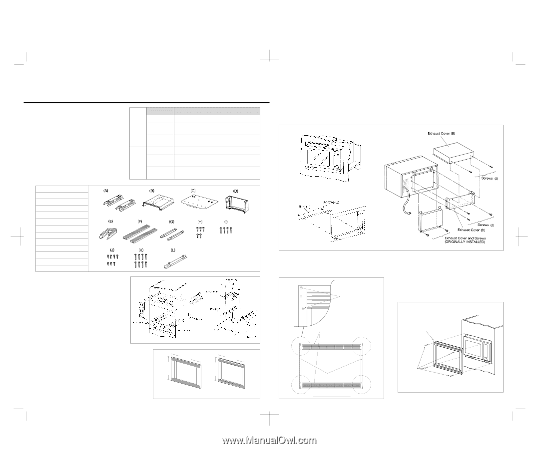
MICROWAVE OVEN BUILT-IN TRIM KITS INSTALLATION INSTRUCTIONS CAUTION 1. Read and follow all instructions completely. 2. This Trim Kit is designed for use only with the Microwave Ovens listed in the table, and where operating instructions make reference to the installation of this Trim Kit. 3. For safe use of your oven, do not alter or modify any part of this kit or oven. 4. Oven must be plugged into a properly grounded 3-prong receptacle as is required by National Electrical Code or any other applicable regulations. 5. Before attempting the installation of this kit, be sure to unplug the oven from wall receptacle. 6. Save these instructions for local inspection and relocation of oven. TRIM KITS OVEN MODELS 30"cabinet NN-TK913S(Metal) NN-C994S, NN-CD989S NN-TK913B(Black) NN-C980B, NN-C988B, NN-9809, NN-9509, NN-9500, NN-9509P NN-9800, NN-9804 NN-TK913W(White) NN-C980W, NN-C988W, NN-9859, NN-9850, NN-9854, NN-9854P MQC1548H 27"cabinet NN-TK903S(Metal) NN-C994S, NN-CD989S NN-TK903B(Black) NN-C980B, NN-C988B, NN-9809, NN-9509, NN-9500, NN-9509P NN-9800, NN-9804 NN-TK903W(White) NN-C980W, NN-C988W, NN-9859, NN-9850, NN-9854, NN-9854P MQC1548H PARTS LIST Quantity (A) Runner 2 (B) Exhaust Cover 1 (C) Base 1 (D) Exhaust Cover 1 (E) Air Guide 1 (F) Top and bottom trim strip ʜ 2 (G) Side trim strip 2 (H) Screw (large diameter) ʜʜ 5 ( I ) Screw (long 4 (J ) Screw (short 7 (K) Screw (small diameter) ʜʜ 8 (L) Blind 1 1. CABINET OPENING 1. The cabinet opening should be as follows. ・Width : 247/8"ʶ1/16" (63.2 cmʶ 0.16 cm) ・Height : 181/16"ʶ1/16" (45.9 cmʶ0.16 cm) ・Depth : 21" (53.3 cm) minimum. Refer to Fig. (1). The overall outside dimensions of 27" type trim kits are 27" (68.6 cm) wide and 30" type trim kits are 30" (76.2 cm) wide and 191/2" (49.6 cm) high for both types of trim kits. Refer to Fig. (3). 2. The floor of the opening must be capable of supporting 100 lbs (45 kg) and should be plywood. 3. The cabinet opening at ceiling should have a clearance of at least 13/4" (4.5 cm) to rear wall W. Refer to Fig. (1). 2. BRACKET INSTALLATION 1. Position Base (C) on the plywood floor, spaced approx. 1/2" (1.3 cm) from the left side and 1/2" (1.3 cm) from the right side. The front end of Base (C) shall be aligned flush with the front edge of the plywood floor. Refer to Fig. (1). 2. Place the two Runners (A) and Air Guide (E) on the Base (C), and secure with the 5 wood Screws (H) onto the plywood floor as shown in Fig. (2). Fig. (1) 30" (76.2 cm) NN-TK913S NN-TK913B NN-TK913W 19 1/2" (49.6 cm) 19 1/2" (49.6 cm) Fig. (2) 27" (68.6 cm) NN-TK903S NN-TK903B NN-TK903W Fig. (3) 3. OVEN PREPARATION 1. Remove two screws and exhaust cover (originally installed) shown in Fig.(6) from the rear of the oven. Retain the Exhaust Cover for future use in case the oven is removed for countertop use. 2. Insert the tab of Exhaust Cover (D) into the slot on the rear of oven and secure with three Screws (J). 3. Place Exhaust Cover (B) on the top of the oven and secure with two Screws (J) shown in Fig.(6). 4. OVEN INSTALLATION 1. Plug the power cord into wall receptacle and slide the oven in on the Runner (A) until the oven rests in the detents of the Runner (A). Use caution so that the cord is not pinched. Fig.(4). 2. Place Blind (L) on the top of Runner (A) and secure with two Screws (J) shown in Fig.(5). Fig. (4) Fig. (5) Fig. (6) 5. TRIM ASSEMBLY 1. Assemble Top & Bottom Trim Strips (F) and two Side Trim Strips (G) by Screws (K) at each of 4 corners of rear side trim (each corner uses 2 screws) . Refer to Fig.(7). Screws (K) 6. TRIM INSTALLATION 1. After the oven is properly installed, center the trim kit frame around the oven. 2. Use the assembled trim kit frame as a template and mark the four holes for drilling pilot holes. 3. Position the trim kit frame and secure to cabinet with Screws ( I ) .Refer to Fig.(8). Top & Bottom Trim Strip (F) TRIM KIT FRAME Fig. (7) Side Trim Strip (G) Rear side of Trim Strip Screws (I) Fig. (8) A0003A951AP 0609 Printed in Japan
-
 1
1
 |
 |