Panasonic NNH275 Microwave - 2.0cuft - English/ Spanish - Page 9
Oven Components Diagram
 |
View all Panasonic NNH275 manuals
Add to My Manuals
Save this manual to your list of manuals |
Page 9 highlights
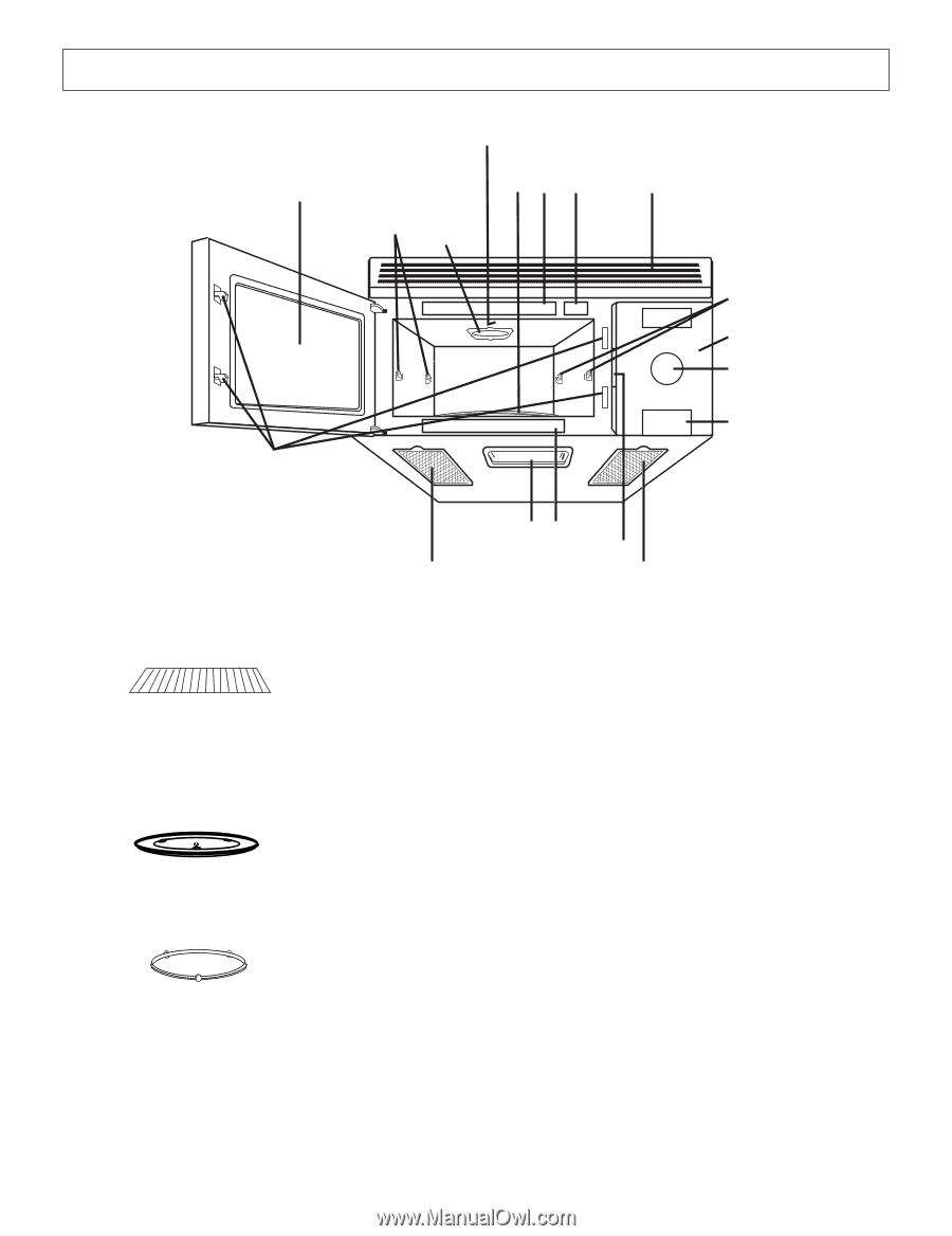
Oven Components Diagram 3 1 4! @ 5 -2 6 7 8 = 9# ~ 0 0 Shelf Shelf can be used for 2-level cooking, see page 19 Glass Tray Roller Ring 1 See-through Oven Window 2 Waveguide Cover (do not remove) 3 Oven Light (Oven Light is replaceable, see page 26) 4 Glass Tray (Turntable) 5 Oven Air Vent (Vent Grille/Vent Grille is removable and can be cleaned, see page 25) 6 Control Panel 7 Pop-Out Dial 8 Door Release Button 9 Cooktop Light (Cooktop Light is replaceable, see page 26) 0 Grease Filter (Grease filter is removable and should be regularly cleaned, see page 26) - Shelf Supports = Door Safety Lock System ~ Identification Plate ! Menu Label @ Notice Label # Function Label 7
-
 1
1 -
2
-
3
-
 4
4 -
 5
5 -
 6
6 -
 7
7 -
 8
8 -
 9
9 -
 10
10 -
 11
11 -
 12
12 -
 13
13 -
 14
14 -
15
-
16
-
17
-
18
-
19
-
20
-
21
-
22
-
23
-
24
-
25
-
26
-
27
-
28
-
29
-
30
-
31
-
32
-
33
-
34
-
35
-
36
-
37
-
38
-
39
-
40
-
41
-
42
-
43
-
44
-
45
-
46
-
47
-
48
-
49
-
50
-
51
-
52
-
53
-
54
-
55
-
56
-
57
-
58
-
59
-
60
-
61
-
62
-
63
-
64
 |
 |
7
Oven Components Diagram
1
2
3
4
5
-
6
7
8
9#
0
=
0
~
!
@
-
1
See-through Oven Window
2
Waveguide Cover
(do not remove)
3
Oven Light
(Oven Light is replaceable, see page 26)
4
Glass Tray
(Turntable)
5
Oven Air Vent
(Vent Grille/Vent Grille is removable and can be
cleaned, see page 25)
6
Control Panel
7
Pop-Out Dial
8
Door Release Button
9
Cooktop Light
(Cooktop Light is replaceable, see page 26)
0
Grease Filter
(Grease filter is removable and should be regularly
cleaned, see page 26)
-
Shelf Supports
=
Door Safety Lock System
~
Identification Plate
!
Menu Label
@
Notice Label
#
Function Label
Shelf
Shelf can
be used for 2-level cooking,
see page 19
Glass Tray
Roller Ring