Panasonic NNSN968B User Manual - Page 12
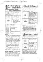
Oven Components Diagram
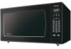 |
View all Panasonic NNSN968B manuals
Add to My Manuals
Save this manual to your list of manuals |
Page 12 highlights
IP1812_38W80CP_11_080220 2008.2.20 16:03 Page 12 Oven Components Diagram i d lg ja b e h d m fk c a External Air Vent b Internal Air Vent c Door Safety Lock System d Exhaust Air Vent e Control Panel f Identification Plate g Glass Tray h Roller Ring i Heat/Vapor Barrier Film (do not remove) j Waveguide Cover (do not remove) k Door Release Button l Warning Label m Menu Label 10
-
 1
1 -
2
-
3
-
4
-
5
-
6
-
 7
7 -
 8
8 -
 9
9 -
 10
10 -
 11
11 -
 12
12 -
 13
13 -
 14
14 -
 15
15 -
 16
16 -
 17
17 -
18
-
19
-
20
-
21
-
22
-
23
-
24
-
25
-
26
-
27
-
28
-
29
-
30
-
31
-
32
-
33
-
34
-
35
-
36
-
37
-
38
-
39
-
40
-
41
-
42
-
43
-
44
-
45
-
46
-
47
-
48
-
49
-
50
-
51
-
52
-
53
-
54
-
55
-
56
-
57
-
58
-
59
-
60
 |
 |

10
Oven Components Diagram
a
External Air Vent
b
Internal Air Vent
c
Door Safety Lock System
d
Exhaust Air Vent
e
Control Panel
f
Identification Plate
g
Glass Tray
h
Roller Ring
i
Heat/Vapor Barrier Film
(do not remove)
j
Waveguide Cover
(do not remove)
k
Door Release Button
l
Warning Label
m
Menu Label
i
d
g
l
j
a
b
e
d
m
f
k
h
c
IP1812_38W80CP_11_080220
2008.2.20
16:03
Page 12