Panasonic PVDF275 PVDF205 User Guide - Page 9
Unit Buttons, Getting Started - pv df275 no power
 |
View all Panasonic PVDF275 manuals
Add to My Manuals
Save this manual to your list of manuals |
Page 9 highlights
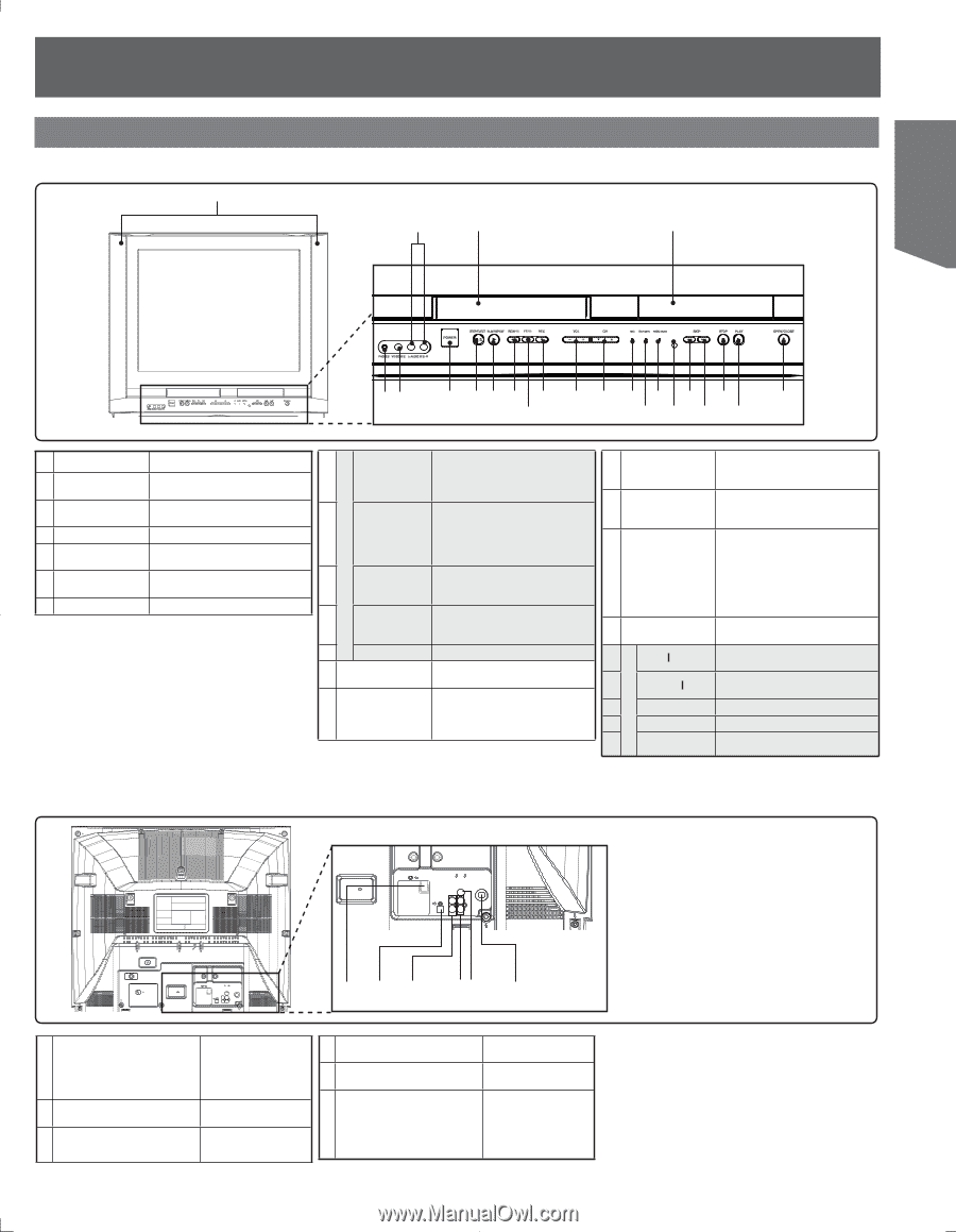
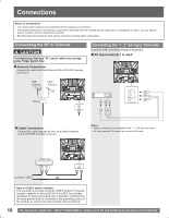
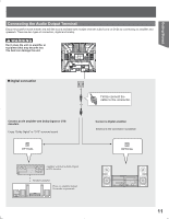
Getting Started DVD Operation VCR Operation Unit Buttons Front View 1 2 3 4 56 7 8 9 10 12 13 14 15 17 19 21 23 11 16 18 20 22 1 Built In Speakers Equipped with 2 front speakers. 2 Audio Input Connector 2 3 Cassette Compartment 4 Disc Tray 5 Phones Jack 6 Video Input Connector 2 Connect from other component. (LINE 2) Insert VHS tapes here. Place compatible discs here. Connect an ear phone or headphones. Connect from other component. (LINE 2) 7 POWER Turns the unit on or off. 8 STOP/ EJECT 9 PLAY/ REPEAT 10 REWIND/ SEARCH FAST 11 FORWARD/ SEARCH 12 REC 13 VOLUME UP/ DOWN CHANNEL UP/ 14 DOWN or TRACKING UP/ DOWN STOP: Stops playback. EJECT: Ejects the tape. PLAY: Begins playback. REPEAT: Set to see a recording over and over. Rewinds tape and searches previous scene. Decreases slow motion speed in Still mode. Fast forwards tape and searches next scene. Increases slow motion speed in Still mode. Records a program. Adjusts volume. Selects a channel. Reduces picture noise during Playback and Slow Motion. 15 REC Indicator (RED) ON TIMER 16 Indicator (ORANGE) PROG TIMER 17 Indicator (GREEN) 18 Remote Sensor 19 SKIP ◄◄ 20 SKIP►► 21 STOP 22 PLAY Lights up during recording. In Rec Pause or OTR Pause mode, the Indicator flashes. Lights when the On Timer is set. Lights up when the unit is set for Timer Recording. It flashes when a Timer Recording has been set with no tape inserted, the clock is not set, or the tape is in motion. Lights up when the On Timer is set. Receives infrared signal from remote control. Skips back one chapter or track. Goes to previous menu screen. Skips one chapter or track. Goes to next menu screen. Stops playback. Begins playback. 23 OPEN/CLOSE Opens or closes the disc tray. Rear View 123 45 6 1 AC Power Plug When plugged into an AC outlet, this unit consumes 0.8 W of electric power in OFF condition. 2 Optical digital audio output Outputs audio signal. connector (Digital) 3 Audio Output Connector (L/R) Outputs audio signal. (Analog) 4 Audio Input Connector 1 5 Video Input Connector 1 6 VHF/UHF Antenna Input Terminal Connect from other component. (LINE 1) Connect from other component. (LINE 1) Input terminal for an antenna or cable box signal. 9
-
 1
1 -
2
-
3
-
 4
4 -
 5
5 -
 6
6 -
 7
7 -
 8
8 -
 9
9 -
 10
10 -
 11
11 -
 12
12 -
 13
13 -
 14
14 -
15
-
16
-
17
-
18
-
19
-
20
-
21
-
22
-
23
-
24
-
25
-
26
-
27
-
28
-
29
-
30
-
31
-
32
-
33
-
34
-
35
-
36
-
37
-
38
-
39
-
40
-
41
-
42
-
43
-
44
-
45
-
46
-
47
-
48
-
49
-
50
-
51
-
52
-
53
-
54
-
55
-
56
-
57
-
58
-
59
-
60
-
61
-
62
-
63
-
64
 |
 |