Panasonic SAHT692 SAHT692 User Guide - Page 8
Step 4 Radio And System Connection, Step 5 The Remote Control
 |
View all Panasonic SAHT692 manuals
Add to My Manuals
Save this manual to your list of manuals |
Page 8 highlights
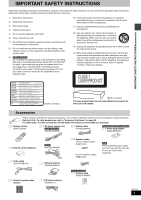
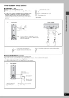
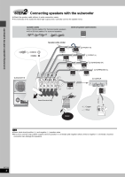
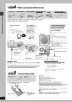
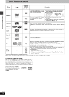
4 STEP Radio and system connection System cable AM loop antenna FM indoor antenna AC power supply cord \U.S.A.\and\Canada] \Others] Power plug adaptor \Areas\except\U.S.A.\and\Canada] Radio and system connection ≥Connect the AC power supply cord after all other connections are complete. ≥Optional antenna connections (‹ page 23). RQT7433 8 FM indoor antenna Adhesive tape Fix the other end of the antenna where reception is best. Click! AM loop antenna Stand the antenna up on its base. Place the antenna where the reception is best. Keep loose antenna cable away from other wires and cables. Subwoofer Main unit AM ANT A LOOP EXT VCR TV LINE COMPONENT VIDEO OUT AUX AUDIO AUDIO OUT (480P/480I) IN IN PB Y L S R PR VIDEO OUT 1 [For[areas[except[U.S.A.[and[Canada[ Before connecting the AC power supply cord Set the voltage. 127 V 110 V 220 V-230 V 240 V VOLT ADJ Use a flat-head screwdriver to turn the voltage selector on the back of the subwoofer to the appropriate position for the area in which this system is used. If the power supply in your area is 115 V or 120 V, please set the voltage selector as follows: ≥For 115 V: Set to 110 V. ≥For 120 V: Set to 127 V. Catch up To disconnect Press the catch and pull out. 2 System cable To disconnect Press the catch and pull out. AC power supply cord To household AC outlet Catch up Conserving power The main unit consumes a small amount of power, even when it is turned off (For U.S.A. and Canada: approx. 0.4 W or for units with PX printed on the outer packaging and Latin America: approx. 0.9 W). To save power when the unit is not to be used for a long time, unplug it from the household AC outlet. You will need to reset some memory items after plugging in the unit. [For\areas\except\U.S.A.\and\Canada] ≥If the power plug will not fit your AC outlet Use the power plug adaptor (included). If it still doesn't fit, contact an electrical parts distributor for assistance. 5 STEP The remote control Remote control Batteries 2 Insert so the poles (i and j) match those in the remote control. 3 Do not: ≥mix old and new batteries. ≥use different types at the same time. ≥heat or expose to flame. ≥take apart or short circuit. ≥attempt to recharge alkaline or manganese batteries. ≥use batteries if the covering has been peeled off. Mishandling of batteries can cause electrolyte leakage which can damage items the fluid contacts and may cause a fire. R6/LR6, AA, UM-3 1 ≥Do not use rechargeable type batteries. Remove if the remote control is not going to be used for a long period of time. Store in a cool, dark place. ∫ Use Aim at the sensor (‹ page 9), avoiding obstacles, at a maximum range of 7 m (23 feet) directly in front of the unit.
-
 1
1 -
2
-
 3
3 -
 4
4 -
 5
5 -
 6
6 -
 7
7 -
 8
8 -
 9
9 -
 10
10 -
 11
11 -
 12
12 -
 13
13 -
14
-
15
-
16
-
17
-
18
-
19
-
20
-
21
-
22
-
23
-
24
-
25
-
26
-
27
-
28
-
29
-
30
-
31
-
32
-
33
-
34
-
35
-
36
 |
 |