Panasonic TC-65CX400 Owners Manual - Page 11
Connections
 |
View all Panasonic TC-65CX400 manuals
Add to My Manuals
Save this manual to your list of manuals |
Page 11 highlights
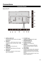
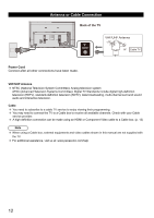
Connections Back of the TV Connection Panels 1. DIGITAL AUDIO OUT Connect to the audio socket on the digital audio system. 2. USB Port Connect to a USB storage device to play compatible audio and photo files. (USB mode) 3. ETHERNET Wired Network connection port. 4. HDMI Inputs Connect to a High-Definition (HD) signal output device. 5. VGA Input Connect to a computer or other devices with a VGA interface. 6. PC AUDIO Input Connect to a computer audio output. 7. ANTENNA/CABLE IN Connect to the antenna. 8. Headphone Socket Connect to the Headphones. 9. AUDIO IN Connect to the composite VIDEO and AUDIO (L/R) input sockets on external video devices. 10. YPbPr/VIDEO Connect to AV devices with component (Y/Pb/Pr) video and audio input sockets. COMPONENT&VIDEO share with AUDIO IN(L/R). Composite video broadcast signal input (Video is shared with Y) 11
-
 1
1 -
2
-
3
-
4
-
5
-
 6
6 -
 7
7 -
 8
8 -
 9
9 -
 10
10 -
 11
11 -
 12
12 -
 13
13 -
 14
14 -
 15
15 -
 16
16 -
17
-
18
-
19
-
20
-
21
-
22
-
23
-
24
-
25
-
26
-
27
-
28
-
29
-
30
-
31
-
32
-
33
 |
 |
