Panasonic TH-50PX80 Operating Instructions - Page 37
Recommended AV Connections
 |
View all Panasonic TH-50PX80 manuals
Add to My Manuals
Save this manual to your list of manuals |
Page 37 highlights
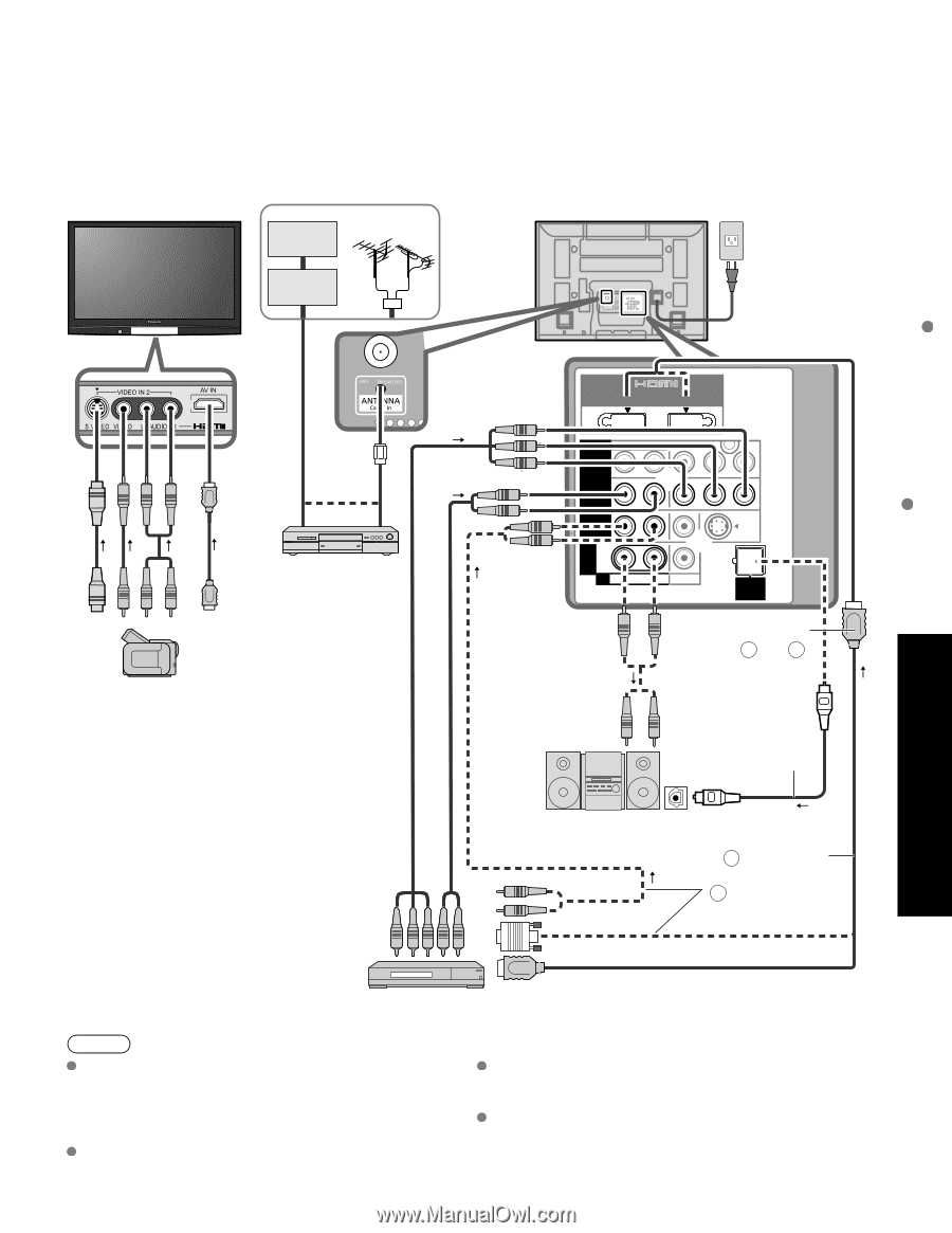
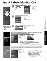
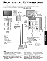
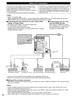
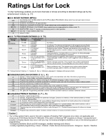
Recommended AV Connections These diagrams show our recommendations on how to connect the TV unit to your various equipment. For other connections, consult the instructions for each piece of equipment and its specifications. For additional assistance, please visit our website at: www.panasonic.com www.panasonic.ca Front of the TV Cable TV or Cable Box Back of the TV AC 120 V 60 Hz AC Cord (Connect after all the other connections are complete.) Recommended AV Connections Using Timer Advanced 3 A COMPONENT IN or or VIDEO IN or ■ DVD Recorder / VCR AV IN HDMI 1 HDMI 2 or 1 COMPONENT R IN 2 R VIDEO IN R PROG OUT TO AUDIO AMP R AUDIO L L L L AUDIO PR PR VIDEO PB Y PB Y S VIDEO DIGITAL AUDIO OUT Connect with A or B ■ To watch camcorder images Camcorder VCR DVD Player (For HDMI connection, HDMI compatible equipment only. For connection using HDMI-DVI Conversion cable, see HDMI 1 or HDMI 2 connection on this page.) Optical digital Amplifier audio cable ■ To listen to the OPTICAL IN TV through speakers A HDMI cable B HDMI-DVI Conversion cable + Audio cable* or ■ To watch DVDs DVD Player/Set Top Box Note The picture and audio input signals connected to a When equipment (STB, DVD, etc.) is connected to terminal specified in "Monitor out" (p. 35) cannot be HDMI or COMPONENT terminals, no video signals can output from "PROG OUT" terminals. be passed through PROG OUT terminal. However, audio output can be obtained from "DIGITAL When receiving digital channel signals, all digital AUDIO OUT" terminal. formats are down-converted to composite NTSC video To prevent howling and image oscillation, set the to be output through the PROG OUT terminals. "Monitor out" setting when connecting the VCR with * Please see p. 22-23 for setup when using an external loop-connection. (p. 24, 35) analog audio cable with an HDMI to DVI cable. 37
-
 1
1 -
2
-
3
-
4
-
5
-
6
-
7
-
8
-
9
-
10
-
11
-
12
-
13
-
14
-
15
-
16
-
17
-
18
-
19
-
20
-
21
-
22
-
23
-
24
-
25
-
26
-
27
-
28
-
29
-
30
-
31
-
 32
32 -
 33
33 -
 34
34 -
 35
35 -
 36
36 -
 37
37 -
 38
38 -
 39
39 -
 40
40 -
 41
41 -
 42
42 -
43
-
44
-
45
-
46
-
47
-
48
-
49
-
50
-
51
-
52
-
53
-
54
-
55
-
56
-
57
-
58
-
59
-
60
-
61
-
62
-
63
-
64
-
65
-
66
-
67
-
68
-
69
-
70
-
71
-
72
-
73
-
74
-
75
-
76
-
77
-
78
-
79
-
80
-
81
-
82
-
83
-
84
-
85
-
86
-
87
-
88
-
89
-
90
-
91
-
92
-
93
-
94
-
95
-
96
-
97
-
98
-
99
-
100
-
101
-
102
-
103
-
104
-
105
-
106
-
107
-
108
-
109
-
110
-
111
-
112
-
113
-
114
-
115
-
116
-
117
-
118
-
119
-
120
-
121
-
122
-
123
-
124
-
125
-
126
-
127
-
128
-
129
-
130
-
131
-
132
-
133
-
134
-
135
-
136
-
137
-
138
-
139
-
140
-
141
-
142
-
143
-
144
-
145
-
146
-
147
-
148
 |
 |