Panasonic TH50PX500U TH42PX500U User Guide - Page 11
Program Out Connection PROG OUT, Amplifier Connection TO AUDIO AMP, Notes, Procedure - instruction manual
 |
View all Panasonic TH50PX500U manuals
Add to My Manuals
Save this manual to your list of manuals |
Page 11 highlights
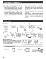
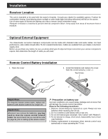
Connection Amplifier Connection (TO AUDIO AMP) For a full Home Theater sound experience, an external Dolby Digital› decoder and a multichannel amplifier must be connected to the DIGITAL AUDIO OUT terminal on the TV. › Dolby Digital 5.1 channel surround sound delivers digital-quality sound. Dolby Digital provides five discrete full- bandwidth channels for front left, front right, center, surround left and surround right, plus a LFE (Low Frequency Effect) subwoofer channel. OPTICAL IN Optical digital audio cable Amplifier or AUDIO INPUT L D I G I TA L AUDIO OUT G-LINK R Audio cable Procedure 1. Select Speakers "Off" in Audio menu (see page 27). 2. Adjust the amplifier volume to the desired level. D I G I TA L AUDIO OUT G - L I AU NK D DI IG O IOTUA TL Back of the TV C a b l e C A R D TM ANTENNA Cable In L R OUTPUT AUDIO OUT AV IN Y Y R L AUDIO IN VIDEO PB PB S VIDEO PC L PR PR VIDEO L AUDIO AUDIO IN R 1 2 COMPONENT VIDEO INPUT INPUT 1 R TO AUDIO AMP INPUT 2 PROGOUT Notes: • Depending on your DVD player and DVD-Audio software the copyright protection function may operate and disable optical output. • External speakers cannot be connected directly to OUTPUT terminals. • When ATSC channel is selected, the output from the DIGITAL AUDIO OUT jack will be Dolby Digital. When NTSC channel is selected, the output will be PCM. Program Out Connection (PROG OUT) See optional equipment manual for further instructions for recording and monitoring. Back of the TV VCR DVD recorder VIDEO INPUT L AUDIO INPUT R AV cable OUTPUT AV IN Y Y R L AUDIO IN VIDEO PB PB S VIDEO PC L PR PR VIDEO L AUDIO AUDIO IN R 1 2 COMPONENT VIDEO INPUT 1 INPUT R TO AUDIO AMP INPUT 2 PROGOUT Notes: • The input signals connected to INPUT1 cannot be output from PROG. OUT terminals. (both picture and audio) However, output can be obtained from optical Digital Audio terminals. (Input signals other than from INPUT1 can be output from PROG. OUT.) • Connect the output of the Video recorder to INPUT1, when recording by using TV GUIDE. • When a device (STB, DVD, etc.) is connected to the HDMI or COMPONENT terminals (see pages 12, 13), only audio signals will be output. No video signals will be output. • When a schedule recording is activated on the TV Guide, the show will be recorded on a connected VCR. Please note that the screen will automatically be switched to the channel of the recorded show. • When receiving digital channel signals, all digital formats are down-converted to composite NTSC video to be output through Program Out terminals. • Some programs contain a Macrovision signal to prevent VCR recording. 11
-
 1
1 -
2
-
3
-
4
-
5
-
 6
6 -
 7
7 -
 8
8 -
 9
9 -
 10
10 -
 11
11 -
 12
12 -
 13
13 -
 14
14 -
 15
15 -
 16
16 -
17
-
18
-
19
-
20
-
21
-
22
-
23
-
24
-
25
-
26
-
27
-
28
-
29
-
30
-
31
-
32
-
33
-
34
-
35
-
36
-
37
-
38
-
39
-
40
-
41
-
42
-
43
-
44
-
45
-
46
-
47
-
48
-
49
-
50
-
51
-
52
-
53
-
54
-
55
-
56
-
57
-
58
-
59
-
60
-
61
-
62
-
63
-
64
-
65
-
66
-
67
-
68
-
69
-
70
-
71
-
72
-
73
-
74
-
75
-
76
-
77
-
78
-
79
-
80
-
81
-
82
-
83
-
84
-
85
-
86
-
87
-
88
-
89
-
90
-
91
-
92
-
93
-
94
-
95
-
96
-
97
-
98
-
99
-
100
-
101
-
102
-
103
-
104
-
105
-
106
-
107
-
108
-
109
-
110
-
111
-
112
-
113
-
114
-
115
-
116
-
117
-
118
-
119
-
120
-
121
-
122
-
123
-
124
-
125
-
126
-
127
-
128
-
129
-
130
-
131
-
132
-
133
-
134
-
135
-
136
-
137
-
138
-
139
-
140
-
141
-
142
-
143
-
144
-
145
-
146
-
147
-
148
-
149
-
150
-
151
-
152
-
153
-
154
-
155
-
156
-
157
-
158
-
159
-
160
-
161
-
162
-
163
-
164
-
165
-
166
-
167
-
168
-
169
-
170
-
171
-
172
-
173
-
174
-
175
-
176
-
177
-
178
-
179
-
180
-
181
-
182
-
183
-
184
-
185
-
186
-
187
-
188
-
189
-
190
-
191
-
192
-
193
 |
 |
