Panasonic WVCP474 WVCP474 User Guide - Page 4
Setting Procedures
 |
View all Panasonic WVCP474 manuals
Add to My Manuals
Save this manual to your list of manuals |
Page 4 highlights
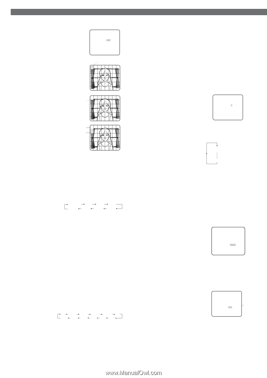
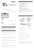
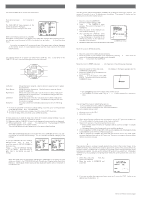
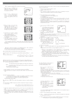
SETTING PROCEDURES 2-2. ALC Mode with SUPER-D2 OFF and ELC Mode Note: If ELC is selected, set MASK SET according to this procedure. 1. Move the cursor to SUPER-D2 and select OFF. (When you select ELC, SUPER-D2 is not available.) The MASK SET appears on the menu. 2. Move the cursor to MASK SET and press SET. The 48 mask areas appear on the monitor screen. The cursor is blinking in the upper left corner of the screen. ** ALC CONT ** BACK LIGHT COMP SUPER-D2 OFF ↵ MASK SET LEVEL ...I..... - + RET END Blinking 3. Move the cursor to the area where backlight is bright and press SET to mask that area. The mask turns to white. (When the cursor is moved on an area that has already been masked, the mask and cursor start blinking.) Blinking 4. Repeat step 3 to mask the desired area. To cancel masking, move the cursor to that area and press SET. 5. After masking is completed, press SET for 2 seconds or more. The ALC CONT menu appears. 6. If you want to change the video output level (picture contrast), move the "I" cursor for LEVEL and adjust the level. Turns to white Blinking Note: If ON is selected for SUPER-D2, a shadow (black line) may appear at the boundary between the bright and the dim scene. This is a natural phenomenon and does not indicate trouble. 3. Shutter Speed Setting (SHUTTER) Note: When ELC is selected for ALC/ELC on the CAM SET UP menu or ON is selected for SUPER-D2 on the ALC CONT menu, this item is not available. To select electronic shutter speed, select OFF for SUPER-D2 in the ALC CONT menu. Move the cursor to SHUTTER and select the electronic shutter speed. The preset values for SHUTTER (electronic shutter speed) change by pressing L or R as fol- lows: The factory default setting is ---. OFF (1/60) 1/100 1/250 1/500 1/10000 1/4000 1/2000 1/1000 4. Gain Control Setting (AGC ON (DNR-H, DNR-L)/OFF) AGC (Automatic Gain Control) automatically controls the gain (an image brightness level). Move the cursor to AGC and select automatic level adjustment ON (DNR-H), ON (DNR-L), or OFF. The factory default setting is ON (DNR-H). ON (DNR-H): This setting raises the gain and brightens the image under low light conditions. ON (DNR-L): This setting reduces an afterimage sometimes caused by a moving object when ON (DNR-H) is activated. OFF: This setting does not control the gain. Notes: • When ON (DNR-L) is selected, noise can slightly increase than ON (DNR-H). • DNR-H and DNR-L do not appear on the system status display of the connected equipment. 5. Electronic Sensitivity Enhancement (SENS UP) There are two modes for SENS UP. AUTO: If you select X10 AUTO, for example, the sensitivity is automatically raised to X10 max. When AUTO is selected, AGC is automatically set to ON. FIX: If you select X32 FIX, for example, the sensitivity is raised to just X32. The factory default setting is OFF. Move the cursor to SENS UP and select the parameter for electronic sensitivity enhancement. The preset values for SENS UP (electronic sensitivity enhancement) change by pressing L or R as shown right: OFF X2 AUTO X4 AUTO X6 AUTO X10 AUTO OFF X32 FIX X16 FIX X10 FIX X6 FIX X4 FIX X2 FIX Notes: • When ON is selected for SUPER-D2 in the ALC CONT menu, FIX is not available for this item. • When you select AUTO for SENS UP and ON for SUPER-D2, the SENS UP function has priority so that the SUPER-D2 function is not activated automatically. • While the SENS UP function is selected, noise, spots or a whitish phenomenon may appear in the picture when the sensitivity of the camera is increased. This is a normal phenomenon. 6. Synchronization Setting (SYNC) You can select internal sync (INT) mode, line-lock (LL) mode or the VD2 signal (multiplexed vertical drive signal) mode. 1. Move the cursor to SYNC and select LL or INT. The factory default setting is INT. 2. Press SET. If LL is selected, the SYNC menu appears. (If VD2 or INT is not selected, the synchronization mode automatically set and the menu does not appear.) Important Notices: 1. The priority for the sync modes is as follows: (1) Multiplexed Vertical Drive (VD2) (Highest priority) (2) Line-lock (LL) (3) Internal Sync (INT) (Lowest priority) 2. The line-lock mode has a submenu for line-lock vertical phase adjustment. If the camera installation is relocated, check the vertical phase adjustment again since the AC line phase may be different. Whenever the multiplexed vertical drive pulse (VD2) is supplied to the camera from external equipment such as a matrix switcher, the camera sync mode is automatically switched to the VD2 mode. 6-1. Line-lock Sync Mode (LL) 1. Move the cursor to SYNC and select LL. ** SYNC ** Note: The settings in this menu can be made only when the multiplexed vertical drive signal (VD2) is not supplied to the camera. V PHASE COARSE FINE 1(1--16) I........ - + 2. After confirming that the cursor is on LL, press SET. The vertical phase RET END adjustment menu appears on the moni- tor screen. 3. Supply the video output signal of the camera to be adjusted and the reference camera video output signal to a dual-trace oscilloscope. 4. Set the oscilloscope to the vertical rate and expand the vertical sync portion on the oscilloscope. 5. Move the cursor to COARSE. The cursor is highlighted. 6. Press L or R to match the vertical phase for both video output signals as closely as possible. (COARSE adjustment can be incremented in 16 steps 1 (1 - - 16): 0 degrees 2 (1 - - 16): 22.5 degrees by 22.5 degrees by pressing L or R.) Note: After the sixteenth step, the adjustment returns to the first step. 16 (1 - - 16): 337.5 degrees 7. Move the cursor to FINE. 8. Press L or R to match the vertical phase for both video output signals as closely as pos- sible. (FINE adjustment can be made by up to 22.5 degrees by pressing L or R.) Notes: • When the "I" cursor reaches the "+" end, it jumps back to "-". At the same time, COARSE is incremented by one step to enable a continuous adjustment. The reverse takes place when the "I" cursor reaches the "-" end. • When L or R is kept pressed for a second or more, the "I" cursor moves faster. • To reset COARSE and FINE to the values preset at the factory, press L and R simultaneously. COARSE and FINE adjustments are preset at the factory to zerocrossing of the AC line phase. • If the AC line contains noise (spike noise, etc.), the stability of the vertical phase of the camera video output signal may be disturbed. 7. White Balance Setting (WHITE BAL) 7-1. Auto-Tracing White Balance Mode (ATW) You can select one of three modes for white balance adjustment as follows: The factory default setting is ATW1. • ATW1 (Auto-Tracing White Balance 1) Move the cursor to WHITE BAL and ** CAM SET UP ** ↵↵ CAMERA ID OFF ALC/ELC ALC SHUTTER --- AGC ON(DNR-H) SENS UP OFF SYNC INT ↵ WHITE BAL ATW1 MOTION DET OFF LENS DRIVE DC select ATW1. In this mode, the color temperature is END SET UP ENABLE monitored continuously and thereby white balance is automatically set. The color temperature range for the proper white balance is approximately 2 600 - 6 000K. Proper white balance may not be obtained under the following conditions: 1. The color temperature is out of the 2 600 - 6 000K range. 2. When the scene contains mostly high color temperature objects, such as a blue sky or sunset. 3. When the scene is dim. In these cases, select the AWC mode. • ATW2 (Auto-Tracing White Balance 2) Auto-tracing white balance in sodium lamp mode (ATW2) When you select ATW2 for sodium lamp, white balance is automatically set (no operation needed). Note: ATW1 and ATW2 do not appear for WHITE BAL on the system controller setup menu. ** CAM SET UP ** ↵↵ CAMERA ID OFF ALC/ELC ALC SHUTTER --- AGC ON(DNR-H) SENS UP OFF SYNC INT WHITE BAL AWC→PUSH SW MOTION DET OFF LENS DRIVE DC END SET UP ENABLE Highlighted • Automatic White Balance Control Mode (AWC) In this mode, accurate white balance is obtained within a color temperature range of approximately 2 300-10 000K. 1. Move the cursor to WHITE BAL and select AWC → PUSH SW. 2. Press SET to start the white balance setup. The PUSH SW is highlighted to indicate that the white balance is being set. 3. When the white balance setting is completed, the PUSH SW returns to normal display. Note: If white balance is not set, the PUSH SW is being highlighted.
-
 1
1 -
 2
2 -
 3
3 -
 4
4 -
 5
5 -
 6
6
 |
 |