Pentair AquaLuminator Above Ground Owners Manual - English - Page 5
Warning - replacement bulb
 |
View all Pentair AquaLuminator manuals
Add to My Manuals
Save this manual to your list of manuals |
Page 5 highlights
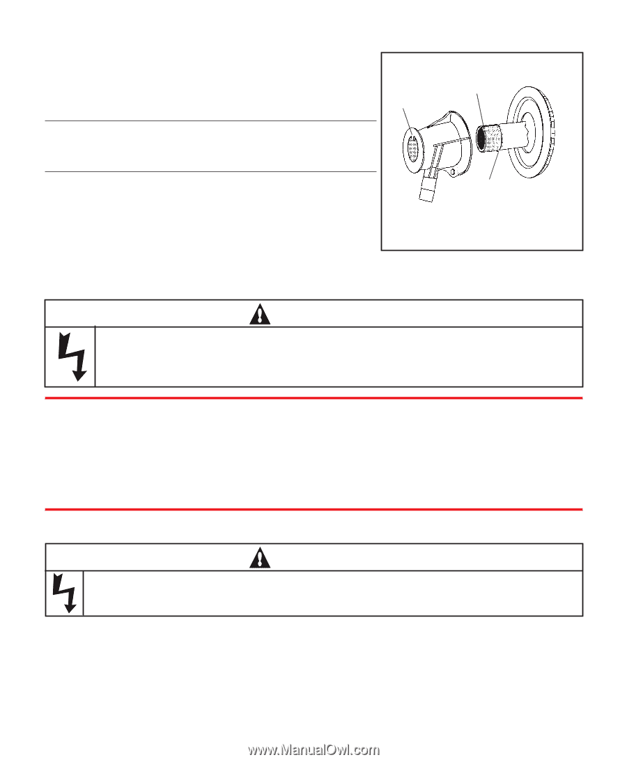
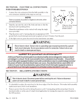
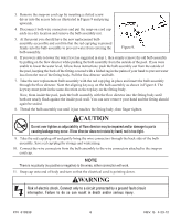
SECTION III. ELECTRICALCONNECTIONS FOR STORABLE POOLS 1. Connect the wire connectors from the bulb assembly to the Key wire connectors attached to the snap-on cord cap. NOTE There is no polarity (no positive or negative) to the wires, either connection will work. Keyway 2. Snap the cap onto the end of the body and turn so that the electrical cord is pointing down. 3. Mount the transformer on the vertical wall using the single screw provided. Figure 8. O-Ring-use silicone lubricant only. Do not use any petroleum products. 4. Plug the power cord's 2-prong plug into an appropriate 220V ground fault circuit interrupter protected receptacle at least 3.0 meters from the pool. 5. If the light is not on, press the switch on the transformer case once. WARNING Risk of electric shock. Connect only to a grounding-type receptacle protected by a ground fault circuit interrupter. Do not use extension cords for connection. Failure to do so can result in death or severe personal injury. øøøWHAT IS A ground fault circuit interrupter??? A ëGround Fault Circuit Interrupterí is an electrical safety device designed to measure electrical leakage in a circuit. It is far more sensitive than a standard circuit breaker. Ground fault circuit interrupter equipped breakers and outlet combinations react to unsafe leakage and shut the power off before electrical shock injury can occur. Any electrical device used within 3.0 meters of a pool must be protected by a ground fault circuit interrupter equipped outlet or a ground fault circuit interrupter equipped circuit breaker and be intended for such use. SECTION IV. RELAMPING INSTRUCTIONS WARNING Risk of electric shock. Disconnect power before servicing this unit. Failure to disconnect power can result in death or severe personal injury. 1. It is desirable to reduce the water level to the lower edge of the flow director. This makes bulb assembly replacement easier, but it is not mandatory. 2. Remove power from the unit by taking the power cord's 2-prong plug and disconnecting it from its electrical outlet, or in the case of a hard-wired application, by turning the respective circuit breaker to the OFF position. Rev. G 4-23-12 5 P/N 619339
-
 1
1 -
 2
2 -
 3
3 -
 4
4 -
 5
5 -
 6
6 -
 7
7 -
 8
8
 |
 |