Philips 200P6EB User manual - Page 10
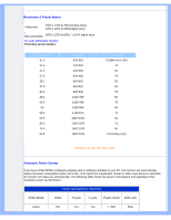
Product Views, V. Sync VCLK for DDC
 |
UPC - 037849960936
View all Philips 200P6EB manuals
Add to My Manuals
Save this manual to your list of manuals |
Page 10 highlights
Product Information 3 T.M.D.S. Data2 Shield 4 NC 5 NC 6 DDC Clock 7 DDC Data 8 * Analog V-sync 11 T.M.D.S. Data1 Shield 12 NC 19 T.M.D.S. Data0 Shield 20 NC 13 NC 14 +5V 15 Ground (return for +5V and H/V-sync) 16 Hot Plug Detect 21 NC 22 T.M.D.S. Clock Shield 23 T.M.D.S. Clock+ 24 T.M.D.S. Clock- C3 * Analog B C4 * Analog H-sync * Analog GND C5 (Analog R, G, B return) 2. The 15-pin D-sub connector (male) of the signal cable: Pin No. Assignment 1 Red video input 2 Green video input/SOG 3 Blue video input 4 Ground 5 Cable detect 6 Red video ground 7 Green video ground 8 Blue video ground Pin No. Assignment 9 +5V 10 Ground 11 Ground 12 Serial data line (SDA) 13 H. Sync / H+V 14 V. Sync (VCLK for DDC) 15 Data clock line (SCL) RETURN TO TOP OF THE PAGE Product Views file:///D|/My%20Documents/dfu/200P6/english/200P6/product/product.htm (5 of 9)2006-01-05 12:24:50 PM
-
 1
1 -
2
-
3
-
4
-
 5
5 -
 6
6 -
 7
7 -
 8
8 -
 9
9 -
 10
10 -
 11
11 -
 12
12 -
 13
13 -
 14
14 -
 15
15 -
16
-
17
-
18
-
19
-
20
-
21
-
22
-
23
-
24
-
25
-
26
-
27
-
28
-
29
-
30
-
31
-
32
-
33
-
34
-
35
-
36
-
37
-
38
-
39
-
40
-
41
-
42
-
43
-
44
-
45
-
46
-
47
-
48
-
49
-
50
-
51
-
52
-
53
-
54
-
55
-
56
-
57
-
58
-
59
-
60
-
61
-
62
-
63
-
64
-
65
-
66
-
67
-
68
-
69
-
70
-
71
-
72
-
73
-
74
-
75
-
76
-
77
-
78
-
79
-
80
-
81
-
82
-
83
-
84
-
85
-
86
-
87
-
88
-
89
-
90
-
91
-
92
-
93
 |
 |
