Philips 26PF5320 Quick start guide - Page 2
Ooking, Elevision - hdmi
 |
UPC - 037849962107
View all Philips 26PF5320 manuals
Add to My Manuals
Save this manual to your list of manuals |
Page 2 highlights
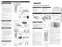
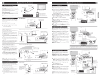
HOOKING UP THE TELEVISION REMOTE CONTROL BATTERY To load the supplied battery into the remote: 1 Remove the plastic isolation sheet from the battery compartment door. 2 Point the remote control at the remote sensor window on the front of the television to operate the television. If television does not respond to the remote control, check the battery in the remote control: 1 Remove the battery compartment door on the back of the remote. 2 Check that the (+) end of the battery (3V) face up correctly. Reattach the battery compartment door. Lithium Battery (3V) Remote Control (shown from the bottom) Battery Compartment Door Plastic Isolation Sheet NOTE: The plastic isolation sheet must be removed for the remote control to function. CABLE/CABLE BOX TV Your Cable TV input into your home may be a single (75 ohm) cable or use a cable box decoder. In either case the connection is very simple. Follow the steps below to connect your cable signal to your new television. Direct Cable Connections: This connection will supply Stereo sound to the TV. 1 Connect the open end of the round Cable Company supplied cable to the 75Ω input on the bottom of the TV. Screw it down finger tight. Direct Cable Connection: Jack Panel Bottom of TV Be sure to point the remote control at the remote sensor window on the front of the television when using the remote control to operate the television. Cable signal coming from Cable Company (Round 75Ω coaxial cable) 1 Cable Box (w/RF In/Outputs): This connection will NOT supply Stereo sound to the TV. The sound from the cable box will be mono. Cable Box with RF Inputs and Outputs Connection: Output Channel Switch 1 Connect the open end of the round Cable Company supplied cable to the cable signal IN(put) plug on the 1 2 back of the Cable Box. 2 Using a separate round coaxial cable, connect one end to the OUT(put) (TO TV) plug on the back of the Cable Box. Jack Panel Back of Cable Box 3 Connect the other end of the round coaxial cable to the 75Ω input on the bottom of the television. Screw it down finger tight. NOTE: Be sure to set the OUTPUT CHANNEL SWITCH on the back of the cable box to CH 3 or 4, then tune the cable box on the TV to the corresponding channel. Once tuned, change channels at the cable box, not the television. Cable Signal IN from the Cable Company Round 75Ω Coaxial Cable Jack Panel Bottom of TV 3 Cable Box (w/Audio/Video Outputs): This connection will supply Stereo sound to the TV. 1 Connect the open end of the round Cable Company supplied cable to the cable signal IN(put) plug on the back of the Cable Box. 2 Using an RCA type Video Cable, connect one end of the cable to the Video (yellow) (or ANT, your cable box may be labeled differently) Out jack on the cable box and the other end to the Video In jack on the bottom of the TV. 3 Using an RCA type Audio Left and Right Cable, connect one end to the left and right Audio Out L & R jacks (red & white) on the cable box and the other ends to the Audio In L & R jacks on the bottom of the TV. NOTE: Use the AV+ button and the CURSOR DOWN/ RIGHT on the TV remote control to tune to the AV channel for the cable box signal. Once tuned, change channels at the cable box, not the television. ANTENNA TV Acombination antenna receives normal broadcast channels (VHF 2-13 and UHF 14-69). Your connection is easy because there is only one 75Ω (ohm) antenna plug on the back of your TV, and that's where the antenna goes. 1 If your antenna has a round cable (75 ohm) on the end, then you're ready to connect it to the TV. If your antenna has flat, twin-lead wire (300 ohm), you first need to attach the antenna wires to the screws on a 300- to 75-ohm adapter. 2 Push the round end of the adapter (or antenna) onto the 75Ω (ohm) plug on the bottom of the TV. If the round end of the antenna wire is threaded, screw it down finger tight. Cable Box with Audio/Video Outputs Connection: Jack Panel Back of Cable Box with A/V Outputs 1 Cable Signal IN from the Cable Company 2 3 Audio Cables L & R (Red, White) Video Cable (Yellow) Antenna Connection: Outdoor or Indoor Antenna (Combination VHF/UHF). The combination antenna receives normal broadcast channels 2-13 (VHF) and 14-69 (UHF). 1 Twin Lead Wire 300 to 75-ohm Adapter Round 75Ω Coaxial Cable from Antenna 2 Jack Panel Bottom of TV Jack Panel Bottom of TV 2 HOOKING UP THE TELEVISION AV INPUTS AV The audio/video input jacks on the bottom panel of the TV are for direct picture and sound connections between the TV and a VCR (or similar device) that has audio/video output jacks. 1 Using an RCA type Video cable, connect one end of the cable to the Video (yellow) Out jack on the VCR or accessory device and the other end to the AV Video In jack on the bottom of the TV. NOTE: A S-Video cable can be used in place of the yellow video cable if your device is equipped with an S-Video Output. S-Video provides better video playback. 5 Using an RCA type Audio Left and Right cable, connect one end 2 to the left and right Audio Out L & R jacks (red & white) on the VCR or accessory device and the other ends to the AV Audio In L & R jacks on the bottom of the TV. 3 Turn the VCR or accessory device and the TV On. 4 4 Press the AV+ button on the remote control to show the Source List menu on the TV screen. 5 Press the CURSOR DOWN button repeatedly until AV is highlighted, then press the CURSOR RIGHT button to enter the selected Mode. 6 With the VCR (or accessory device) ON and a prerecorded tape (CD, DVD, etc.) inserted, press the PLAY button to view the tape on the television. COMPONENT (CVI) INPUTS CVI Component Video inputs provide the highest possible color and picture resolution in the playback of digital signal source material, such as with DVD players. 1 Connect the Component (Y, Pb, Pr) Video OUT jacks from the DVD player (or similar device) to the CVI-1 VIDEO Input (Y green, Pb blue, Pr red) jacks on the bottom of the TV. 2 Connect the red and white AUDIO CABLES on the rear of the TV to the Audio (left and right) output jacks on the rear of the accessory device. 3 Turn the TV and the DVD player (or digital accessory device) ON. 5 4 Press the AV+ button on the remote control to show the Source List menu on the TV screen. 5 Press the CURSOR DOWN button repeatedly until CVI-1 is highlighted, then press the CURSOR RIGHT button to enter the selected Mode. 4 6 Insert a DVD disc into the DVD player and press the PLAY π button on the DVD Player. TUNE TO AV CHANNEL 1 VIDEO IN (YELLOW) 5 AUDIO IN (RED/WHITE) VCR (or accessory device) (EQUIPPED WITH VIDEO AND AUDIO OUTPUT JACKS) 2 6 3 Jack Panel Bottom of TV 5 Jack Panel Bottom of TV 1 AUDIO CABLES (RED/WHITE) ACCESSORY DEVICE EQUIPPED WITH COMPONENT VIDEO OUTPUTS. 6 3 2 COMPONENT VIDEO CABLES (Green, Blue, Red) HELPFUL HINT The description for the component video connectors may differ depending on the DVD player or accessory digital source equipment used (for example, Y, Pb, Pr; Y, B-Y, R-Y; Y, Cr, Cb). Refer to your DVD player or digital accessory owner's manual for definitions and connection details. HD (HIGH DEFINITION) INPUTS If you are using a High Definition receiver that can transmit high definition programming, the TV can accept those signals through the HD Inputs located on the bottom of the TV. 1 For Digital Connection, connect the HDMI connector of the HD Receiver (or similar device) to the HDMI Input jacks on the bottom of the TV. OR 2 For Analog Connection, use Component Video cables to connect the Component (Y, Pb, Pr) Video Out jacks of the HD Receiver (or similar device) to the VGA adapter (supplied with the TV). Connect the other end of the adapter to the VGA Input jacks on the bottom of the TV. 3 Connect the red and white audio cable to RCA type Audio Cables. Connect the audio adapter to the PC Audio In L & R jacks on the bottom of the TV. 4 Turn the TV and the HD Receiver ON. 5 Press the AV+ button on the remote control to show the Source List menu on the TV screen. 6 Press the CURSOR DOWN button repeatedly until HDMI (for digital connections) or CVI-2 (for analogue connections) is highlighted, then press the s button to enter the selected mode. NOTE: The Audio/Video cables needed for this connection are not supplied with your TV. Please contact your dealer or Philips at 1-888 PHILIPS (744-5477) for information about purchasing the needed cables. HDMI 6 5 3 1 6 Digital Connection AUDIO CABLES HDMI CABLE HD RECEIVER EQUIPPED WITH 4 COMPONENT VIDEO OUTPUTS. 3 2 Analog Connection COMPONENT VIDEO CABLES (Green, Blue, Red) Rear of HD Receiver (Illustration is for reference only. Your HD Receiver's jack panel may be labeled differently. Coxial Cable Lead-in from Cable Outlet, Cable Converter Box, or VHF/ UHF Antenna Coaxial cable Lead-in from Satellite Dish or Antenna English
-
 1
1 -
 2
2
 |
 |
