Philips 32PF9996 User manual - Page 23
Connect Accessory Devices, Recorder (vcr-dvd+rw), Recorder and other A/V devices, Recorder
 |
View all Philips 32PF9996 manuals
Add to My Manuals
Save this manual to your list of manuals |
Page 23 highlights
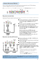
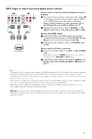
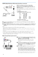
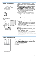
Connect Accessory Devices There is a wide range of audio and video devices that can be connected to your TV.The following connection diagrams show you how to connect them to the TV. AV1 can handle YPbPr,Y/C and CVBS; AV2 YPbPr (RGB), CVBS and Y/C; HDMI (AV3) ; Side: CVBS and Y/C. AV2 AV1 R Pr/R Y/G V S-VIDEO R Pr MONITOR OUT AUDIO RECEIVER Y R CENTRE R AV3 R HDMI ANT IN 75 L Pb/B CVBS H S-VIDEO L Pb VIDEO L SUBW. L L Recorder (VCR-DVD+RW) Note: Do not place your recorder too close to the screen as some recorders may be susceptible for signals from the display. Keep a minimum distance of 20" from the screen. AV2 R Pr/R Y/G V ANT IN 75 L Pb/B CVBS H S-VIDEO & Connect the RF Antenna or Cable TV cable (eventually via an optional two-way signal splitter and/or Cable TV converter box) 1 to the RF IN socket of your recorder. é Connect another RF cable 2 from the output OUT of your recorder to the TV's input 75 ø x jack. CABLE " Better playback quality can be obtained if you also connect the Video, Audio Left and Right (only for stereo 3 devices) AV cables 3 to the CVBS, AUDIO L and R input jacks of AV2. OUT OUT IN RECORDER If your recorder has an S-VHS video jack: For improved picture quality, connect an S-video cable with the S-VIDEO input instead of connecting the recorder to the CVBS jack of AV2. S-Video does not provide audio, so audio cables must still be connected to provide sound. Recorder and other A/V devices AV2 R Pr/R Y/G AV1 V S-VIDEO R Pr MONITOR OUT YR ANT IN 75 L Pb/B CVBS H S-VIDEO L Pb VIDEO L 5 4 OUT 6 3 IN 2 OUT IN RECORDER & Connect the RF antenna cable 1 of the RF IN socket of your other AV device. é Connect the RF output of the AV device to the RF input of the recorder 2. " Connect another RF cable 4 from the output OUT of your recorder to the TV's input 75 Ohm x jack. ' To obtain better quality, also connect the Video or CABLE S-Video,Audio left and Audio right cables of both devices to AV1 (Y or S-VIDEO, AUDIO L and R,) 3 and to AV2 (CVBS or S-VIDEO, AUDIO L and R) 5. 1 Notes: - In case of mono equipment, only the left loudspeaker reproduces sound. Use a mono to stereo adapter (not supplied) for sound reproduction via all internal loudspeakers. - When using the S-VIDEO connector do not connect any device to the AV2 CVBS or AV1 Y input. The MONITOR OUT connector can be used for a daisy chaining or to record programs from your TV 6. Only when a recorder is connected to MONITOR OUT it is possible to record a program from your TV. See Record with your recorder, p. 24. 19
-
 1
1 -
2
-
3
-
4
-
5
-
6
-
7
-
8
-
9
-
10
-
11
-
12
-
13
-
14
-
15
-
16
-
17
-
 18
18 -
 19
19 -
 20
20 -
 21
21 -
 22
22 -
 23
23 -
 24
24 -
 25
25 -
 26
26 -
 27
27 -
 28
28 -
29
-
30
-
31
-
32
-
33
-
34
-
35
-
36
-
37
-
38
 |
 |
