Philips 42PF7320A User manual - Page 33
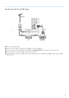
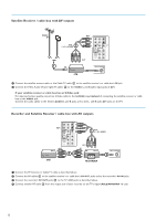
Recorder and cable box with RF output
 |
UPC - 037849962572
View all Philips 42PF7320A manuals
Add to My Manuals
Save this manual to your list of manuals |
Page 33 highlights
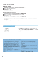
Recorder and cable box with RF output ble CARD INTERFACE CABLE H Pr L V Pb R SIGNAL SPLITTER NETWORK VIDEO AV1 S-VIDEO Y DIGITAL AUDIO IN AV3 VIDEO Pr S-VIDEO AV2 L Pb R Y HDMI 1 2 HDMI 2 CABLE / ANTENNA 75 DIGITAL AUDIO OUT MONITOR OUT L R VIDEO IR OUT 4 AV2 : L + R + VIDEO 1 IN OUT 3 IN OUT STB RECORDER & Use an optional signal splitter. é Connect one of the cable TV signal splitter outputs 1 to the cable box's IN jack. " Connect the other cable TV signal splitter output 2 to the CABLE/ANTENNA 75 Ω x plug on the bottom of the TV. ' Connect the cable box's OUT jack 3 to the recorders RF IN socket. ( Connect the Video, Audio Left and Right (only for stereo sound) recorder AV cables 4 to the VIDEO, audio L and R input AV2 jacks on the TV. 31
-
 1
1 -
2
-
3
-
4
-
5
-
6
-
7
-
8
-
9
-
10
-
11
-
12
-
13
-
14
-
15
-
16
-
17
-
18
-
19
-
20
-
21
-
22
-
23
-
24
-
25
-
26
-
27
-
 28
28 -
 29
29 -
 30
30 -
 31
31 -
 32
32 -
 33
33 -
 34
34 -
 35
35 -
 36
36 -
 37
37 -
 38
38 -
39
-
40
-
41
-
42
-
43
-
44
-
45
-
46
-
47
-
48
 |
 |
