Philips 50PF7320A User manual - Page 35
DVD Player or other accessory digital source devices - review
 |
UPC - 037849962619
View all Philips 50PF7320A manuals
Add to My Manuals
Save this manual to your list of manuals |
Page 35 highlights
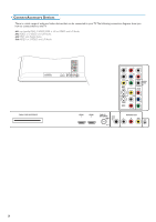
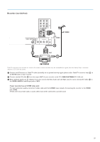
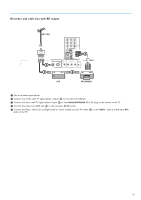
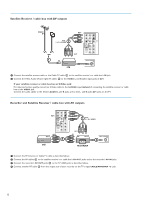
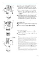
AV1/AV3 : YPbPr 1 AV1 H Pr L YPbPr V Pb R VIDEO Y AV1 S-VIDEO AV3 S-VIDEO AV2 VIDEO Pr L Pb R Y AV3 AV1 : L + R DIGITAL AUDIO IN 3 2 DVD / STB AV1 : H + V 3 AV1 : YPbPr 1 RGB H Pr L V Pb R VIDEO AV1 S-VIDEO Y DIGITAL AUDIO IN AV3 VIDEO Pr S-VIDEO AV2 L Pb R Y AV1 : L + R 2 DVD / STB S-VIDEO H Pr L V Pb R AV1 VIDEO Y S-VIDEO AV1 DIGITAL AUDIO IN AV3 AV1/AV2 : S-VIDEO VIDEO Pr S-VIDEO L Pb AV2 R Y AV2 1 AV1/AV2 : L + R 2 DVD / STB DVD Player or other accessory digital source devices Devices with Component Video Output Connectors (YPbPr) This TV is capable of displaying 1080i, 720p and 480p DTV signals when connected to a DTV tuner Set Top Box. Select the output of the Set Top Box to either 1080i, 720p or 480p. A DTV signal must be available in your area. & Connect the three separate component video cables 1 to the device having component video outputs (YPbPr), such as Set Top Boxes, DVDplayers, laser-disc players, videogame players, satellite receivers or other equipment, and to the Y, Pb and Pr jacks of AV1 or AV3 on the TV. • Connect to the Y, Pb and Pr jacks of AV1 in case of devices with analog audio signals. • Connect to the Y, Pb and Pr jacks of AV3 in case of devices with digital audio signals. é In case of a device with digital audio, connect the audio cable 2 to the DIGITAL AUDIO OUT of the device and to the DIG. AUDIO IN of the TV or to your Home Cinema system. In case of a device with analog audio, connect the audio cable to the device's AUDIO L and R 3 jacks and the L and R audio jacks of AV1. Devices with RGB output & Connect the device with RGB output with separate Horizontal and Vertical sync to the Pr/R Pb/B Y/G input 1 jacks and to the H and V jacks of AV1 2. é Connect the audio cables to the L and R AUDIO jacks of AV1 3. Devices with an S-Video connector & Connect an S-Video cable to the AV1 or AV2 S-VIDEO input 1. Note: When using the S-VIDEO connector do not connect any device to the AV VIDEO input that you are using. é Connect the audio cables to the device's AUDIO L and R jacks and to the L and R audio AV1 or AV2 jacks 2 on the TV accordingly to where you connected the S-Video cable. Notes - If necessary, you can adjust the picture position to the center of the screen with the cursor keys. - The labels for the component video sockets may differ depending on the DVD player or the device connected. Although the abbreviations may vary, the letters B and R stand for the blue and red component signals, respectively, and Y indicates the luminance signal. Refer to the DVD player's or devices instructions for use for definitions and connection details. - This television is designed to accept high definition signal standards 720p and 1080i as specified by the Electronic Industries Association standard EIA770.3. Digital devices from different manufacturers have the possibility of differing output standards which may cause difficulties for the television to properly display. - Due to possible digital image distortion when displaying signals from connected digital equipment, automatically the Auto picture setting Soft is selected. See Picture menu, Auto picture, p. 19. Changing this setting during reviewing will not be stored as Personal setting after switch off. Warning: in case you notice scrolling images, wrong colors or no color, no picture, or even combinations of these on your screen, check if the connections are done in the correct way or move your digital device further away from your TV. 33
-
 1
1 -
2
-
3
-
4
-
5
-
6
-
7
-
8
-
9
-
10
-
11
-
12
-
13
-
14
-
15
-
16
-
17
-
18
-
19
-
20
-
21
-
22
-
23
-
24
-
25
-
26
-
27
-
28
-
29
-
 30
30 -
 31
31 -
 32
32 -
 33
33 -
 34
34 -
 35
35 -
 36
36 -
 37
37 -
 38
38 -
 39
39 -
 40
40 -
41
-
42
-
43
-
44
-
45
-
46
-
47
-
48
 |
 |
