Philips DVD782CH98 User manual - Page 15
Rear Panel
 |
View all Philips DVD782CH98 manuals
Add to My Manuals
Save this manual to your list of manuals |
Page 15 highlights
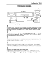
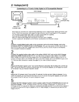
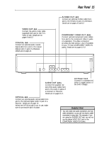
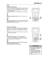
VIDEO OUT Jack Connect the yellow video cable (supplied) here and to the TV's Video In jack. Details are on pages 9 and 12. COAXIAL Jack Connect an optional audio coaxial digital cable here and to the coaxial digital Audio In jack of a Receiver. Details are on page 12. Rear Panel 15 S-VIDEO OUT Jack Connect an optional S-Video cable here and to the S-Video In jack of a television. Details are on pages 10 and 12. COMPONENT VIDEO OUT Jacks Connect optional component video cables here and to the component Video In jacks of a television. This video connection provides the best picture. Use it if possible (if your TV has COMPONENT VIDEO IN jacks). Details are on pages 11-12. PCM-DOLBY DIGITAL-DTS OPTICAL COAXIAL DIGITAL AUDIO OUT 2 1 R L VIDEO S-VIDEO AUDIO OUT OUT OUT Y Pb/Cb Pr/Cr COMPONENT VIDEO OUT AUDIO OUT Jacks Connect the supplied red and white audio cables here and to the Audio In jacks of a television or Receiver. Details are on pages 9-11. AC Power Cord Connect to a standard AC outlet to supply power to the DVD Changer. OPTICAL Jack Connect an optional audio optical cable here and to the Optical Digital Audio In jack of a Receiver. Details are on page 12. When the OPTICAL jack is not in use, make sure its protective cap is in place. Helpful Hint • You only need one audio connection and one video connection, so you will not have a cable connected to every jack. For example, if you are using the S-VIDEO OUT jack, you will not use the yellow VIDEO OUT jack or the COMPONENT VIDEO OUT jacks.
-
 1
1 -
2
-
3
-
4
-
5
-
6
-
7
-
8
-
9
-
 10
10 -
 11
11 -
 12
12 -
 13
13 -
 14
14 -
 15
15 -
 16
16 -
 17
17 -
 18
18 -
 19
19 -
 20
20 -
21
-
22
-
23
-
24
-
25
-
26
-
27
-
28
-
29
-
30
-
31
-
32
-
33
-
34
-
35
-
36
-
37
-
38
-
39
-
40
-
41
-
42
-
43
-
44
-
45
-
46
-
47
-
48
-
49
-
50
-
51
-
52
-
53
-
54
-
55
 |
 |
