Philips MANT940 User Manual - Page 5

Parts Included, Mounting Instructions - installation

Page 5 highlights

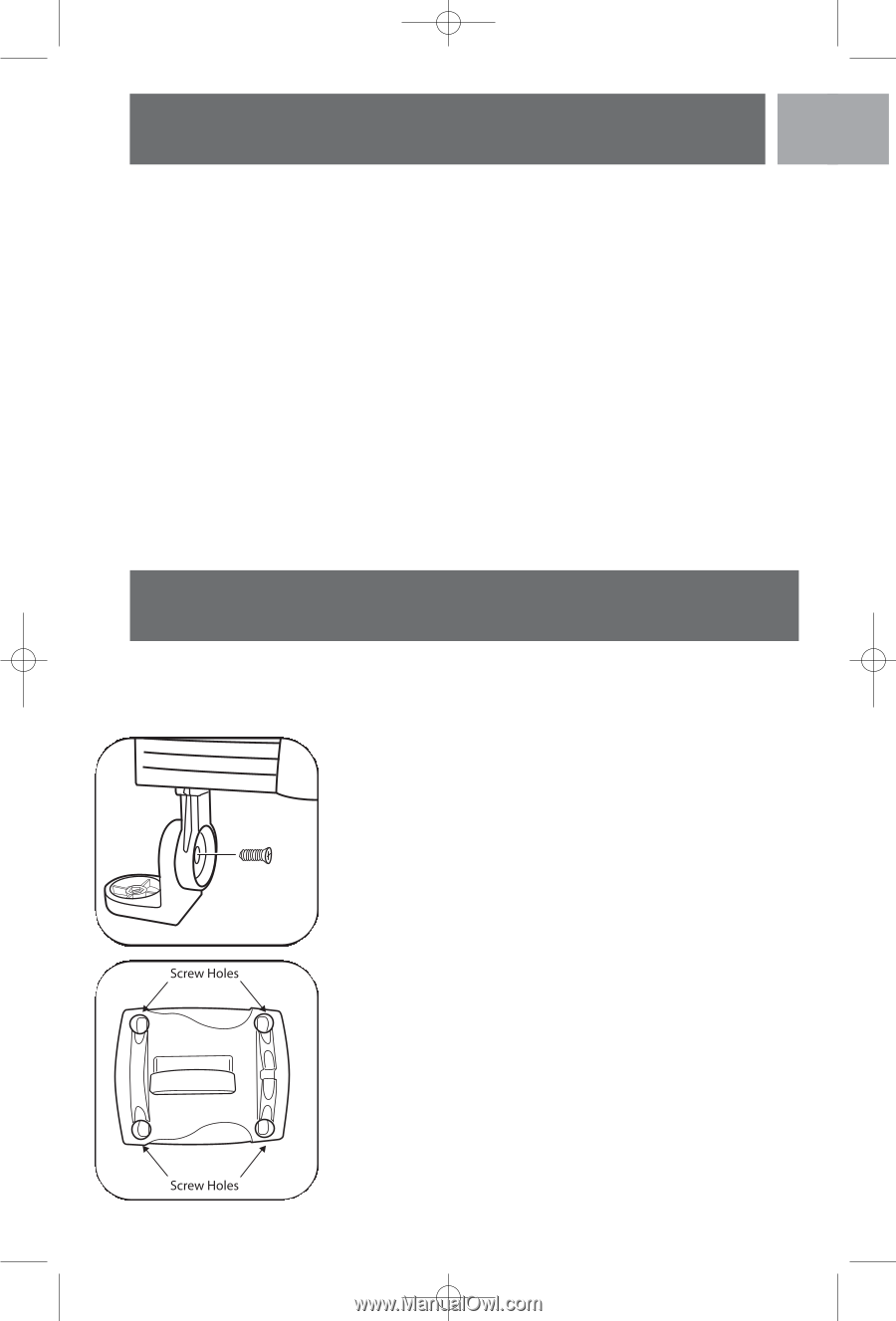
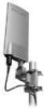
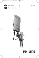
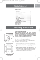
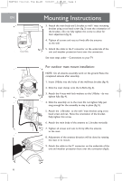
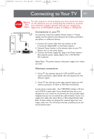
MANT940 Instruct Eng Sp_SM 10/8/07 4:38 PM Page 5 Parts Included EN Parts included: 1. MANT940 Antenna 1 2. Power supply 120V to 6VDC 1 3. Wall / Mast Bracket 1 4. Nuts 2 5. U-Bolts 2 6. Mast clamps 2 7. Nuts with lock washers 4 7. L-Bracket 1 8. 2" Wood Screws 4 9. 20' coax cable with connectors 1 10. Weather Boot 1 11. Power Injector 1 12. Plastic Anchors 4 Mounting Instructions Determining signal strength Before Installation determine the best location for optimum reception. It is important for the antenna to have an unobstructed path to the transmitter.To determine the transmitter(s) location you can consult the website http://www.antennaweb.org. For best results the antenna should be facing the transmitter location. For indoor wall mount installation: NOTE: Do all antenna assembly work on the ground before fig.1 installing on a wall or an antenna mast. 1. Attach main body to the L - bracket as shown, using cross head screw note the orientation of the bracket. Do not fully tighten the screw to allow for later adjustment (fig. 1). 2. Using the Wall/Mast bracket as a guide, mark position for the four 2" wood screws. If possible locate a stud to screw into. If a stud is not available, use appropriate wall anchors (not included, available at any hardware store) (fig. 2). fig.2 Wall Mount 5

  • 1
  • 2
  • 3
  • 4
  • 5
  • 6
  • 7
  • 8
  • 9
  • 10
  • 11
  • 12
  • 13
  • 14
  • 15
  • 16

Parts included:
1.
MANT940 Antenna
. . . . . . . . . . . . . . . . . . . . 1
2.
Power supply 120V to 6VDC
. . . . . . . . . . . . 1
3.
Wall / Mast Bracket. . . . . . . . . . . . . . . . . . . . 1
4.
Nuts
. . . . . . . . . . . . . . . . . . . . . . . . . . . . . . . . 2
5.
U-Bolts . . . . . . . . . . . . . . . . . . . . . . . . . . . . . . 2
6.
Mast clamps
. . . . . . . . . . . . . . . . . . . . . . . . . . 2
7.
Nuts with lock washers . . . . . . . . . . . . . . . . . 4
7.
L-Bracket. . . . . . . . . . . . . . . . . . . . . . . . . . . . . 1
8.
2" Wood Screws. . . . . . . . . . . . . . . . . . . . . . . 4
9.
20' coax cable with connectors. . . . . . . . . . . 1
10. Weather Boot
.........................
1
11. Power Injector . . . . . . . . . . . . . . . . . . . . . . . . 1
12. Plastic Anchors . . . . . . . . . . . . . . . . . . . . . . . . 4
Determining signal strength
Before Installation determine the best location for optimum
reception. It is important for the antenna to have an unobstructed
path to the transmitter.To determine the transmitter(s) location you
can consult the website http://www.antennaweb.org.For best results
the antenna should be facing the transmitter location.
For indoor wall mount installation:
NOTE:
Do all antenna assembly work on the ground before
installing on a wall or an antenna mast.
1.
Attach main body to the L – bracket as shown, using cross
head screw note the orientation of the bracket. Do not fully
tighten the screw to allow for later adjustment (fig. 1).
2.
Using the Wall/Mast bracket as a guide, mark position for the
four 2” wood screws. If possible locate a stud to screw into.
If a stud is not available, use appropriate wall anchors (not
included, available at any hardware store) (fig. 2).
EN
Parts Included
5
Mounting Instructions
Wall Mount
fig.1
fig.2
MANT940 Instruct Eng Sp_SM
10/8/07
4:38 PM
Page 5