Pioneer AVIC U310BT Installation Manual - Page 12
Connecting the power cord 2, Connecting the System - applications
 |
UPC - 012562956299
View all Pioneer AVIC U310BT manuals
Add to My Manuals
Save this manual to your list of manuals |
Page 12 highlights
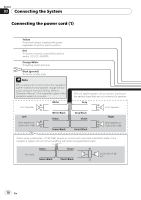
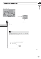
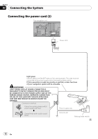
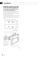
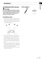
Section 03 Connecting the System Connecting the power cord (2) The navigation unit Power cord Light green Used to detect the ON/OFF status of the parking brake. This lead must be connected to the power supply side of the parking brake switch. If this connection is made incorrectly or omitted, certain functions of your navigation system will be unusable. WARNING LIGHT GREEN LEAD AT POWER CONNECTOR IS DESIGNED TO DETECT PARKED STATUS AND MUST BE CONNECTED TO THE POWER SUPPLY SIDE OF THE PARKING BRAKE SWITCH. IMPROPER CONNECTION OR USE OF THIS LEAD MAY VIOLATE APPLICABLE LAW AND MAY RESULT IN SERIOUS INJURY OR DAMAGE. Connection method Clamp the parking brake switch power supply side lead. Power supply side Clamp firmly with needle-nosed pliers. Ground side Parking brake switch 12 En
-
 1
1 -
2
-
3
-
4
-
5
-
6
-
 7
7 -
 8
8 -
 9
9 -
 10
10 -
 11
11 -
 12
12 -
 13
13 -
 14
14 -
 15
15 -
 16
16 -
 17
17 -
18
-
19
-
20
-
21
-
22
-
23
-
24
-
25
-
26
-
27
-
28
-
29
-
30
-
31
-
32
-
33
-
34
-
35
-
36
-
37
-
38
-
39
-
40
-
41
-
42
-
43
-
44
-
45
 |
 |
