Pioneer DEH 1900MP Other Manual - Page 2
Connecting the Units, ENGLISH, Installation - remote
 |
UPC - 012562840390
View all Pioneer DEH 1900MP manuals
Add to My Manuals
Save this manual to your list of manuals |
Page 2 highlights
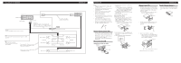
Connecting the Units ENGLISH This Product Rear output Antenna jack Yellow Connect to the constant 12 V supply terminal. Fuse (10 A) Blue/white Connect to system control terminal of the power amp or auto-antenna relay control terminal (max. 300 mA 12 V DC). Connect with RCA cables (sold separately) Power amp (sold separately) System remote control Red Connect to terminal controlled by ignition switch (12 V DC). Black (chassis ground) Connect to a clean, paint-free metal location. With a 2 speaker system, do not connect anything to the speaker leads that are not connected to speakers. + Front speaker ≠ Left + Rear speaker ≠ White White/black Green Green/black Gray Gray/black Violet Violet/black + Front speaker ≠ Right + Rear speaker ≠ Perform these connections when using the optional amplifier. + Rear speaker ≠ + Rear speaker ≠ Installation Note: • Check all connections and systems before final installation. • Do not use unauthorized parts. The use of unauthorized parts may cause malfunctions. • Consult with your dealer if installation requires drilling of holes or other modifications of the vehicle. • Do not install this unit where: - it may interfere with operation of the vehicle. - it may cause injury to a passenger as a result of a sudden stop. • The semiconductor laser will be damaged if it overheats. Install this unit away from hot places such as near the heater outlet. • Optimum performance is obtained when the unit is installed at an angle of less than 60°. 60° DIN Front/Rear-mount This unit can be properly installed either from "Front" (conventional DIN Front-mount) or "Rear" (DIN Rear-mount installation, utilizing threaded screw holes at the sides of unit chassis). For details, refer to the following installation methods. DIN Front-mount Installation with the rubber bush Dashboard Mounting sleeve 182 53 Rubber bush Screw 1. Insert the mounting sleeve into the dashboard. • When installing in a shallow space, use a supplied mounting sleeve. If there is enough space behind the unit, use factory supplied mounting sleeve. 2. Secure the mounting sleeve by using a screwdriver to bend the metal tabs (90°) into place. 3. Install the unit as illustrated. Removing the Unit 1. Extend top and bottom of the trim ring outwards to remove the trim ring. (When reattaching the trim ring, point the side with a groove downwards and attach it.) • It becomes easy to remove the trim ring if the front panel is released. Trim ring 2. Insert the supplied extraction keys into both sides of the unit until they click into place. 3. Pull the unit out of the dashboard. ENGLISH DIN Rear-mount 1. Extend top and bottom of the trim ring outwards to remove the trim ring. (When reattaching the trim ring, point the side with a groove downwards and attach it.) • It becomes easy to remove the trim ring if the front panel is released. Fastening the front panel If you do not plan to detach the front panel, the front panel can be fastened with supplied screw. Trim ring Screw 2. Determine the appropriate position where the holes on the bracket and the side of the unit match. 3. Tighten two screws on each side. • Use either truss screws (5 mm × 8 mm) or flush surface screws (5 mm × 9 mm), depending on the shape of screw holes in the bracket. Screw Dashboard or Console Factory radio mounting bracket
-
 1
1 -
 2
2 -
 3
3 -
 4
4
 |
 |
