Pioneer DEH-2800 Service Manual - Page 54
General Information, 7.1 Diagnosis, 7.1.1 Disassembly, Diagnosis
 |
View all Pioneer DEH-2800 manuals
Add to My Manuals
Save this manual to your list of manuals |
Page 54 highlights
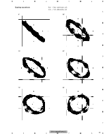
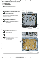
1 2 3 4 7. GENERAL INFORMATION 7.1 DIAGNOSIS 7.1.1 DISASSEMBLY A - Removing the Case (not shown) 1. Remove the Case. - Removing the CD Mechanism Module (Fig.1) CD Mechanism Module 1 Remove the four screws. B Disconnect the connector and then remove the 1 CD Mechanism Module. 1 - Removing the Grille Assy (Fig.1) 2 Release the two latchs and then remove the Grille Assy. C 1 2 1 2 - Removing the Tuner Amp Unit (Fig.2) 1 Remove the screw. D 2 Remove the three screws. 3 Straighten the tabs at three locations indicated and then remove the Tuner Amp Unit. E 2 1 Grille Assy Fig.1 2 2 F 54 1 3 3 Tuner Amp Unit 3 Fig.2 DEH-2800MP/XN/UC 2 3 4
-
 1
1 -
2
-
3
-
4
-
5
-
6
-
7
-
8
-
9
-
10
-
11
-
12
-
13
-
14
-
15
-
16
-
17
-
18
-
19
-
20
-
21
-
22
-
23
-
24
-
25
-
26
-
27
-
28
-
29
-
30
-
31
-
32
-
33
-
34
-
35
-
36
-
37
-
38
-
39
-
40
-
41
-
42
-
43
-
44
-
45
-
46
-
47
-
48
-
 49
49 -
 50
50 -
 51
51 -
 52
52 -
 53
53 -
 54
54 -
 55
55 -
 56
56 -
 57
57 -
 58
58 -
 59
59 -
60
-
61
-
62
-
63
-
64
-
65
-
66
-
67
-
68
-
69
-
70
-
71
-
72
 |
 |

DEH-2800MP/XN/UC
54
1
2
3
4
1
2
3
4
C
D
F
A
B
E
7. GENERAL INFORMATION
7.1
DIAGNOSIS
7.1.1
DISASSEMBLY
-
Removing the CD Mechanism Module (Fig.1)
1
Fig.1
-
Removing the Case (not shown)
Grille Assy
-
Removing the Grille Assy (Fig.1)
1. Remove the Case.
CD Mechanism Module
1
1
1
1
Fig.2
Tuner Amp Unit
-
Removing the Tuner Amp Unit (Fig.2)
Remove the screw.
1
Remove the four screws.
Disconnect the connector and then remove the
CD Mechanism Module.
2
Release the two latchs and then remove
the Grille Assy.
2
2
1
2
2
2
3
3
3
Remove the three screws.
2
Straighten the tabs at three locations
indicated and then remove
the Tuner Amp Unit.
3