Pioneer DEH-80PRS Installation Manual - Page 3
Power amp sold separately, Connections - manual
 |
View all Pioneer DEH-80PRS manuals
Add to My Manuals
Save this manual to your list of manuals |
Page 3 highlights
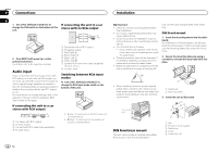
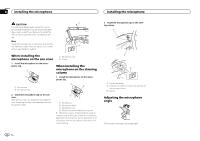
Connections Connections Section 01 English Power amp (sold separately) Standard mode with internal amp Important ! Change the DSP switch to standard mode (STD). For more details on change settings, refer to the operation manual or Switching the DSP setting mode on this page. ! The following signals are output from the speaker leads when this connection is in use. White: Front left + White/black: Front left * Gray: Front right + Gray/black: Front right * Green: Rear left + Green/black: Rear left * Violet: Rear right + Violet/black: Rear right * 1 3 2 4 5 5 1 System remote control Connect to Blue/white cable. 2 Power amp (sold separately) 3 Connect with RCA cable (sold separately) 4 To subwoofer output 5 Subwoofer Standard mode without internal amp Important ! Change the DSP switch to standard mode (STD). For more details on change settings, refer to the operation manual or Switching the DSP setting mode on this page. ! If using this system, we recommend that this unit's internal amp is turned off. For details, refer to the operation manual. ! The speaker leads are not used when this connection is in use. 1 3 2 4 5 5 3 1 2 6 7 7 3 2 1 8 9 9 1 System remote control Connect to Blue/white cable. 2 Power amp (sold separately) 3 Connect with RCA cable (sold separately) 4 To Rear output 5 Rear speaker 6 To Front output 7 Front speaker 8 To subwoofer output 9 Subwoofer 3-way network mode with internal amp Important ! Change the DSP switch to 3-way network mode (NW). For more details on change settings, refer to the operation manual or Switching the DSP setting mode on this page. ! The following signals are output from the speaker leads when this connection is in use. White: Middle range left + White/black: Middle range left * Gray: Middle range right + Gray/black: Middle range right * Green: High range left + Green/black: High range left * Violet: High range right + Violet/black: High range right * 1 3 2 4 5 5 1 3 2 4 5 5 3 1 2 6 7 7 3 2 1 8 9 9 1 System remote control Connect to Blue/white cable. 2 Power amp (sold separately) 3 Connect with RCA cable (sold separately) 4 To low range output 5 Low range speaker 3-way network mode without internal amp Important ! Change the DSP switch to 3-way network mode (NW). For more details on change settings, refer to the operation manual or Switching the DSP setting mode on this page. ! If using this system, we recommend that this unit's internal amp is turned off. For details, refer to the operation manual. ! The speaker leads are not used when this connection is in use. 1 System remote control Connect to Blue/white cable. 2 Power amp (sold separately) 3 Connect with RCA cable (sold separately) 4 To high range output 5 High range speaker 6 To middle range output 7 Middle range speaker 8 To low range output 9 Low range speaker Switching the DSP setting mode This unit features two operation modes: the 3way network mode (NW) and the standard mode (STD). You can switch between modes as desired. Initially, the DSP setting is set to the standard mode (STD). ! After switching, reset the microprocessor. WARNING Do not use the unit in standard mode when a speaker system for 3-way network mode is connected to this unit. This may cause damage to the speakers. En 3
-
 1
1 -
 2
2 -
 3
3 -
 4
4 -
 5
5 -
 6
6 -
 7
7 -
 8
8 -
 9
9 -
10
-
11
-
12
-
13
-
14
-
15
-
16
-
17
-
18
-
19
-
20
 |
 |
