Pioneer DEH-P3600 Other Manual - Page 2
Connecting the Units, <ENGLISH> - manual
 |
UPC - 012562668499
View all Pioneer DEH-P3600 manuals
Add to My Manuals
Save this manual to your list of manuals |
Page 2 highlights
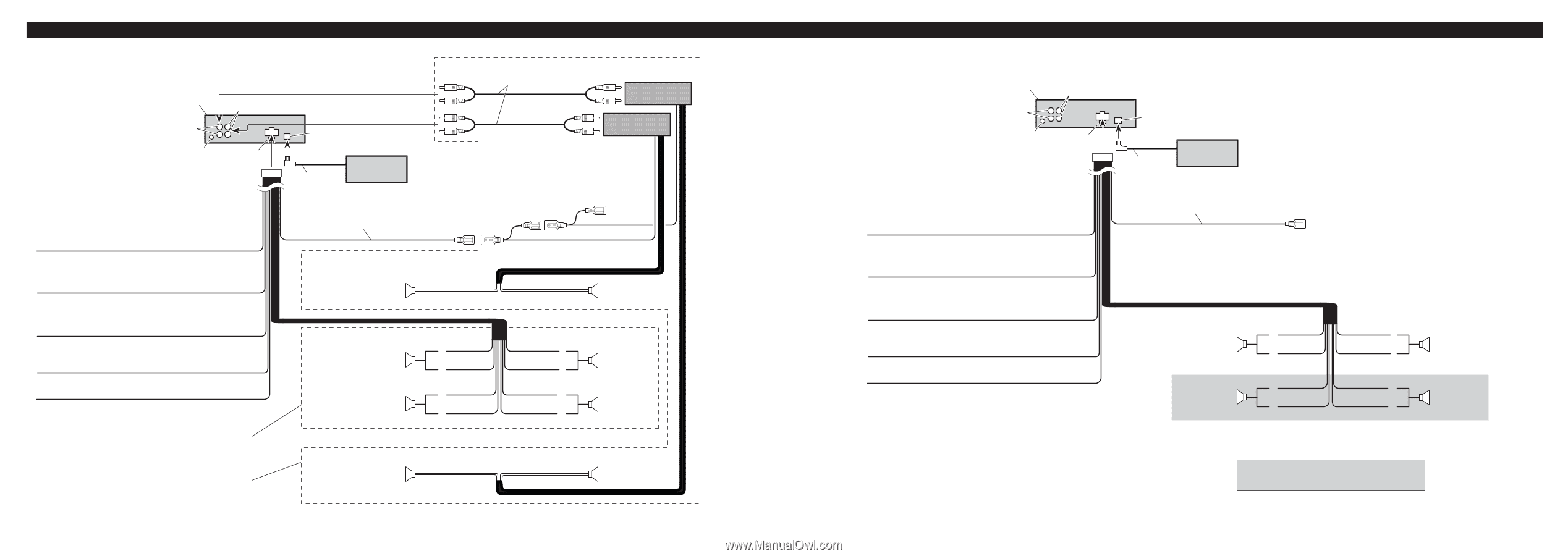
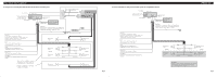
Connecting the Units 7 When not connecting a rear speaker lead to a Subwoofer This product Front output Subwoofer output or non fading output Antenna jack Fuse Yellow/black If you use a cellular telephone, connect it via the Audio Mute lead on the cellular telephone. If not, keep the Audio Mute lead free of any connections. Yellow To terminal always supplied with power regardless of ignition switch position. Red To electric terminal controlled by ignition switch (12 V DC) ON/OFF. Orange/white To lighting switch terminal. Black (ground) To vehicle (metal) body. With a 2 speaker system, do not connect anything to the speaker leads that are not connected to speakers. Perform these connections when using the optional amplifier. Connecting cords with RCA pin plugs (sold separately) IP-BUS input (Blue) IP-BUS cable Multi-CD player (sold separately) Blue/white To system control terminal of the power amp or Auto-antenna relay control terminal (max. 300 mA 12 V DC). System remote control Power amp (sold separately) Power amp (sold separately) + Front speaker ≠ + Front speaker ≠ Front speaker Left Rear speaker White + ≠ White/black + Green ≠ Green/black Gray Gray/black Violet Violet/black + Front speaker ≠ Right + Rear speaker ≠ + Subwoofer ≠ + Subwoofer ≠ Fig. 2 7 When using a Subwoofer without using the optional amplifier This product Front output Subwoofer output Antenna jack Fuse IP-BUS input (Blue) IP-BUS cable Multi-CD player (sold separately) Blue/white To system control terminal of the power amp or Auto-antenna relay control terminal (max. 300 mA 12 V DC). Yellow/black If you use a cellular telephone, connect it via the Audio Mute lead on the cellular telephone. If not, keep the Audio Mute lead free of any connections. Yellow To terminal always supplied with power regardless of ignition switch position. Red To electric terminal controlled by ignition switch (12 V DC) ON/OFF. Orange/white To lighting switch terminal. Black (ground) To vehicle (metal) body. Front speaker Left Subwoofer White + ≠ White/black + Green ≠ Green/black Gray Gray/black Violet Violet/black + Front speaker ≠ Right + Subwoofer ≠ Note: Change the initial setting of this unit (refer to the Operation Manual). The subwoofer output of this unit is monaural. Fig. 3
-
 1
1 -
 2
2 -
 3
3 -
 4
4 -
 5
5 -
 6
6 -
 7
7
 |
 |