Pioneer DEH-P470MP Other Manual - Page 2
Connecting the Units, <ENGLISH> - manual
 |
View all Pioneer DEH-P470MP manuals
Add to My Manuals
Save this manual to your list of manuals |
Page 2 highlights
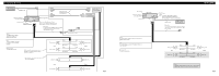
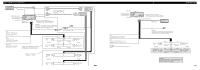
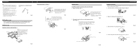
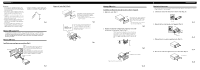
Connecting the Units Multi-CD player (sold separately) IP-BUS cable Connecting cords with RCA pin plugs (sold separately) Subwoofer output or non fading output This product IP-BUS input (Blue) Antenna jack Fuse Front output (FRONT OUTPUT) Jack for the Wired Remote Control Please see the Instruction Manual for the Wired Remote Control (sold separately). Blue/white To system control terminal of the power amp or Auto-antenna relay control terminal (max. 300 mA 12 V DC). Yellow To terminal always supplied with power regardless of ignition switch position. Red To electric terminal controlled by ignition switch (12 V DC) ON/OFF. Black (ground) To vehicle (metal) body. With a 2 speaker system, do not connect anything to the speaker leads that are not connected to speakers. System remote control + Front speaker ≠ Left + Rear speaker ≠ White White/black Green Green/black Gray Gray/black Violet Violet/black Power amp (sold separately) Power amp (sold separately) + Front speaker ≠ Right + Rear speaker ≠ Perform these connections when using the optional amplifier. + Subwoofer ≠ Left + Front speaker ≠ + Subwoofer ≠ Right + Front speaker ≠ Fig. 2 This product Subwoofer output or non fading output Antenna jack Front output Fuse IP-BUS input (Blue) Jack for the Wired Remote Control Please see the Instruction Manual for the Wired Remote Control (sold separately). IP-BUS cable Multi-CD player (sold separately) Blue/white To system control terminal of the power amp or Auto-antenna relay control terminal (max. 300 mA 12 V DC). Yellow To terminal always supplied with power regardless of ignition switch position. Red To electric terminal controlled by ignition switch (12 V DC) ON/OFF. Black (ground) To vehicle (metal) body. + Front speaker ≠ Left + Subwoofer ≠ White White/black Green Green/black Gray Gray/black Violet Violet/black + Front speaker ≠ Right + Subwoofer ≠ Note: Change the initial setting of this unit (refer to the Operation Manual). The subwoofer output of this unit is monaural. Fig. 3
-
 1
1 -
 2
2 -
 3
3 -
 4
4 -
 5
5 -
 6
6 -
 7
7
 |
 |
