Pioneer DEH-P800PRS Other Manual - Page 3
Connection diagram for 3-way network mode with internal amp, Connection diagram for 3-way network
 |
UPC - 012562883724
View all Pioneer DEH-P800PRS manuals
Add to My Manuals
Save this manual to your list of manuals |
Page 3 highlights
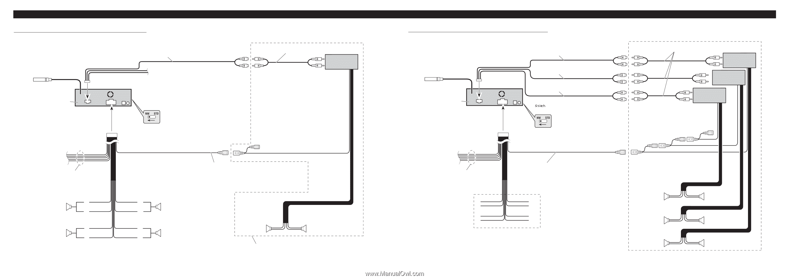
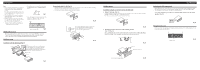
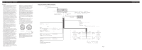
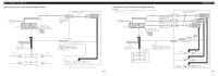
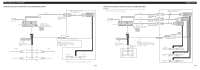
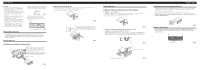
Connecting the Units Connection diagram for 3-way network mode with internal amp 23 cm (9 in.) Antenna jack This product DSP switch Switch the DSP switch as illustration below. Low range output (LOW/SUBWOOFER OUTPUT) Connecting cords with RCA pin plugs (sold separately) Power amp (sold separately) Connection diagram for 3-way network mode without internal amp Note: • If using this system, we recommend that this unit's internal amp is turned off. For more details, refer to operation manual. 23 cm (9 in.) Antenna jack 15 cm (5-7/8 in.) 15 cm (5-7/8 in.) Low range output (LOW/SUBWOOFER OUTPUT) High range output (HIGH/REAR OUTPUT) This product DSP switch Switch the DSP switch as illustration below. Middle range output (MID/FRONT OUTPUT) Connecting cords with RCA pin plugs (sold separately) Power amp (sold separately) Power amp (sold separately) Power amp (sold separately) Power cable (For details, refer to Fig. 2.) Left + Middle range speaker ≠ + High range speaker ≠ FL + FL - RL + RL - System remote control Blue/white To system control terminal of the power amp or Auto-antenna relay control terminal (max. 300 mA 12 V DC). FR + FR - RR + RR - Right + Middle range speaker ≠ + High range speaker ≠ Left + Low range speaker ≠ Right + Low range speaker ≠ Perform this connection when using the optional amplifier. Fig. 5 Power cable (For details, refer to Fig. 2.) FL + FL - RL + RL - Blue/white To system control terminal of the power amp or Auto-antenna relay control terminal (max. 300 mA 12 V DC). Speaker leads Not used. FR + FR - RR + RR - System remote control Left + Middle range speaker ≠ + High range speaker ≠ + Low range speaker ≠ Right + Middle range speaker ≠ + High range speaker ≠ + Low range speaker ≠ Fig. 6
-
 1
1 -
 2
2 -
 3
3 -
 4
4 -
 5
5 -
 6
6 -
 7
7 -
 8
8
 |
 |