Pioneer DJM 1000 Owner's Manual - Page 7
Connecting To The Effector And Output Connectors, Midi Connectors - dj mixer
 |
UPC - 012562703862
View all Pioneer DJM 1000 manuals
Add to My Manuals
Save this manual to your list of manuals |
Page 7 highlights
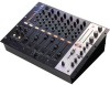
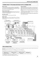
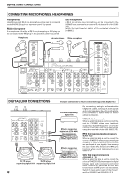
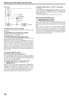
BEFORE USING (CONNECTIONS) CONNECTING TO THE EFFECTOR AND OUTPUT CONNECTORS Master output There is an XLR plug correspondent balanced output MASTER 1, and a RCA plug correspondent unbalanced output MASTER 2. Set the output level using the MASTER ATT. dial to match the input sensitivity of the connected power amplifier. Booth monitor output Unbalanced output supporting Ø6.3 mm phone plug. Volume can be adjusted with the BOOTH MONITOR dial (LEVEL), regardless of the setting of the MASTER fader. Recording output Output connectors for recording, supports RCA plug. Digital output Coaxial digital output connector, supports RCA plug. Sampling frequency can be selected (96 kHz/48 kHz) in accordance with connected device. External effector Use a cable with Ø6.3 mm phone plugs to connect the DJ mixer's SEND connectors to the input connectors of an external effector. When using a monaural input effector, connect only the L channel output. In this way, the mixed L/R audio signal will be sent to the effector. In the same way, use a cable with Ø6.3 mm phone plugs to connect the DJ mixer's RETURN connectors to the output connectors of the external effector. When the effector has only monaural output, connect the L channel input only. In this way, the signal from the effector will be input to both L/R channels. Power amplifier (RCA plug input connector) Cassette deck, etc. (analog input recording device) External effector (2) MASTER ATT. RL LR POWER OFF ON OUTPUT 3COLD MASTER ATT. 2 HOT 1 0dB GND -3dB 6 -6dB -12dB PHONO CD / LINE MASTER 2 REC L L L R MASTER 1 R SIGNAL GND. 5 PHONO CD / LINE L R INPUT 4 PHONO CD / LINE SIGNAL GND. 3 PHONO CD / LINE L L R R 2 PHONO CD / LINE L R SIGNAL GND. 1 PHONO CD / LINE L R L BOOTH (TRS) R R SUBMIC SUBMIC L (MONO) LINE R L (MONO) LINE R L (MONO) LINE R L (MONO) LINE R AC IN DIGITAL OUT fs(Hz) CONTROL DIGITAL CONTROL DIGITAL CONTROL DIGITAL CONTROL DIGITAL CONTROL SOUND 2 CONTROL SOUND 1 48k 96k 2 SEND 1 L (MONO) MIDI OUT R L (MONO) VISUAL R 2 RETURN 1 EFX 2 EFX 1 48k/96k External effector (1) Power amplifier (XLR plug input connector) Digital input AV amplifier (Digital input recording device) Power amplifier (For booth monitor) MIDI CONNECTORS MIDI (Musical Instrument Digital Interface) is a unified standard for transmitting data between electrical musical instruments and computers. Data can be transmitted between devices with MIDI connectors using a MIDI cable. The DJM-1000 can send operating data to external MIDI devices using the MIDI protocol. DJM-1000 control Cross fader operation MIDI control code CC11 MIDI control name Expression MIDI Channel 1 * 0-127 MIDI data is output by operating the cross fader. * When using the visual link function, MIDI data is not output. 7
-
 1
1 -
 2
2 -
 3
3 -
 4
4 -
 5
5 -
 6
6 -
 7
7 -
 8
8 -
 9
9 -
 10
10 -
 11
11 -
 12
12 -
13
-
14
-
15
-
16
-
17
-
18
-
19
-
20
 |
 |