Pioneer DJM-850 Operation Manual - Page 8
Connecting input terminals, Connecting output terminals - used
 |
View all Pioneer DJM-850 manuals
Add to My Manuals
Save this manual to your list of manuals |
Page 8 highlights
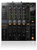
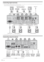
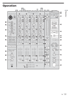
Connecting input terminals ! When creating a DVS (Digital Vinyl System) combining a computer, audio interface, etc., be careful in connecting the audio interface to this unit's input terminals and in the settings of the input selector switches. Also refer to the operating instructions of the DJ software and audio interface. Analog player Cassette deck, CD player, etc. (line level output devices) Analog player Microphones LR LR LR LR OFF POWER ON AC IN RETURN R L (MONO) CH 4 PHONO CD/ LINE L CH 3 LINE CD/ LINE L SIGNAL GND CH 2 LINE CD/ LINE L CH 1 PHONO CD/ LINE L SIGNAL GND MIC2 MIDI OUT SEND R L (MONO) R MASTER1 R R R MASTER2 REC OUT LL L BOOTH TRS R L R CONTROL DIGITAL MASTER OUT CH3 CH1 R R 1 GND 2 HOT 3 COLD CH4 CH2 LR LR LR LR To power outlet Pioneer DJ players ! To use the fader start function, connect a control cable (page 15). Connecting output terminals Pioneer DJ players OFF POWER ON AC IN RETURN R L (MONO) CH 4 PHONO CD/ LINE L CH 3 LINE CD/ LINE L SIGNAL GND CH 2 LINE CD/ LINE L CH 1 PHONO CD/ LINE L SIGNAL GND MIC2 MIDI OUT SEND R L (MONO) R MASTER1 R R R MASTER2 REC OUT LL L BOOTH TRS R L R CONTROL DIGITAL MASTER OUT CH3 CH1 R R 1 GND 2 HOT 3 COLD CH4 CH2 LR LR Power amplifier Power amplifier Cassette deck, etc. Power amplifier External effector 1 (analog input (for booth monitor) recording device) 1 Also connect the external effector to the [RETURN] terminal (input terminal). Digital audio input device MIDI sequencer 8 En
-
 1
1 -
2
-
 3
3 -
 4
4 -
 5
5 -
 6
6 -
 7
7 -
 8
8 -
 9
9 -
 10
10 -
 11
11 -
 12
12 -
 13
13 -
14
-
15
-
16
-
17
-
18
-
19
-
20
-
21
-
22
-
23
-
24
-
25
-
26
-
27
-
28
-
29
-
30
-
31
-
32
 |
 |
