Pioneer DMH-2600NEX Installation Manual - Page 4
Speaker leads, Power amp sold, separately, iPod®/iPhone® and, smartphone, iPod/iPhone with,
 |
View all Pioneer DMH-2600NEX manuals
Add to My Manuals
Save this manual to your list of manuals |
Page 4 highlights
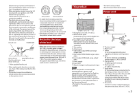
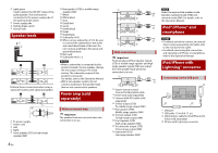
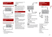
Light green Used to detect the ON/OFF status of the parking brake. This lead must be connected to the power supply side of the parking brake switch. Power supply side Parking brake switch Ground side Speaker leads Perform these connections when using a subwoofer without the optional amplifier. Rear speaker (STD) or middle range speaker (NW) White White/black Gray Gray/black Green Green/black Violet Violet/black Subwoofer (4 Ω) When using a subwoofer of 2 Ω, be sure to connect the subwoofer to the violet and violet/black leads of this unit. Do not connect anything to the green and green/black leads. Not used. Subwoofer (4 Ω) × 2 NOTES • When a subwoofer is connected to this product instead of a rear speaker, change the rear output setting in the initial setting. The subwoofer output of this product is monaural. For details, refer to the Operation Manual. • With a two-speaker system, do not connect anything to the speaker leads that are not connected to speakers. Power amp (sold separately) To power supply Power cord Left Right Front speaker (STD) or high range speaker (NW) 4 En Without internal amp Important The speaker leads are not used when this connection is in use. With internal amp Important Front speaker and Rear speaker signals (STD) or middle range speaker and high range speaker signals (NW) are output from the speaker leads when this connection is in use. System remote control Connect to Blue/white cable. Power amp (sold separately) Connect with RCA cable (sold separately) To Rear output (STD) To middle range output (NW) Rear speaker (STD) Middle range speaker (NW) To Front output (STD) To high range output (NW) Front speaker (STD) High range speaker (NW) To subwoofer output (STD) To low range output (NW) Subwoofer (STD) Low range speaker (NW) NOTE Select the appropriate speaker mode between standard mode (STD) and network mode (NW). For details, refer to the Operation Manual. iPod®/iPhone® and smartphone NOTES • For details on how to connect an external device using a separately sold cable, refer to the manual for the cable. • For details concerning the connection and operations of iPhone or smartphone, refer to the Operation Manual. iPod/iPhone with Lightning® connector Connecting via the USB port USB port USB cable 1.5 m (4 ft. 11 in.) USB interface cable for iPod/iPhone (CDIU52) (sold separately) iPhone with Lightning connector
-
 1
1 -
 2
2 -
 3
3 -
 4
4 -
 5
5 -
 6
6 -
 7
7 -
 8
8 -
 9
9 -
 10
10 -
11
-
12
-
13
-
14
-
15
-
16
-
17
-
18
-
19
-
20
-
21
-
22
-
23
-
24
-
25
-
26
-
27
-
28
 |
 |
