Pioneer DRM-3000 User Manual for the DVD-7361 drive - Page 7
A Hardware Tour
 |
View all Pioneer DRM-3000 manuals
Add to My Manuals
Save this manual to your list of manuals |
Page 7 highlights
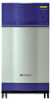
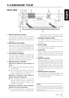
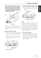
A HARDWARE TOUR REAR VIEW 1 2 34 5 6 7 English ON SCSI ID WIRING MONITOR IND SCSI TERM IND BLOCK SIZE TERM ON / OFF BLOCK SIZE OFF 512 byte ON 2048 byte RELEASE LOCK 8 1 SCSI termination switch This switch is used to turn the drive's internal SCSI termination switch on and off. Note that this switch is set on at the time of shipment. 2 Data block size switch This switch is used to set the data block size. When this switch is turned on the data block size is set to a length of 2048 bytes, and when it is set off the data block size is set to a length of 512 bytes. 3 Termination indicator When the drive is installed in a changer and its power cable has been connected, this indicator lights up if the drive's SCSI termination switch has been turned on. 4 Wiring monitor indicator Meaning of indicator when indicator is lit up: ¶ Indicates that a disc has been inserted into the drive. ¶ This indicator also lights up when the drive is installed in a changer and its power cable has been connected. Meaning of indicator when indicator flashes in 2-second intervals: ¶ This indicator flashes in 2-second intervals when the drive is installed in a changer and its changer interface cable has been connected. Meaning of indicator when indicator flashes in 0.5-second intervals: ¶ This indicator flashes in 0.5-second intervals when the drive in question has 9 been specified as the drive to be swapped during the swapping of drives. 5 Changer interface cable This cable must be connected to the changer-internal changer interface connector. 6 Power cable This cable must be connected to the power inlet located in the changer. 7 Lock lever When a drive is to be removed from the changer, flip the lock lever to the released position and then pull the drive out from the changer. 8 SCSI ID switches These switches are used to set the drive's SCSI ID. Pressing the upper switch causes the displayed SCSI ID to be decremented, and pressing the lower switch conversely causes the SCSI ID to be incremented. Note that SCSI ID is set to '0' at the time of shipment. 9 SCSI interface connector This connector must be connected to the SCSI cable provided with the changer or to an add-on SCSI cable. NOTE: Be careful not to allow any part of your body to come into contact with connector pins, as doing so may result in faulty connections or damage from static electricity. 7 En
-
 1
1 -
 2
2 -
 3
3 -
 4
4 -
 5
5 -
 6
6 -
 7
7 -
 8
8 -
 9
9 -
 10
10 -
 11
11
 |
 |
