Pioneer DV-414 Service Manual - Page 44
Adjustment
 |
View all Pioneer DV-414 manuals
Add to My Manuals
Save this manual to your list of manuals |
Page 44 highlights
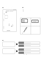
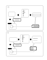
DV-515, DV-414 6. ADJUSTMENT 6.1 ADJUSTMENT ITEMS AND LOCATION Adjustment Points (PCB Part) DVDM ASSY CN9030 CN9020 SIDE A IC904 5 1 1 VC901 Adjustment Items [Electrical Part] 1 16MHz Master Clock Adjustment 2 VCO Offset Adjustment IC801 MB86371C CN120 CN201 1, 2 : Focus Error 3, 4 : GND 5, 6 : RF 7 : S REQ 8 : 3.3V 9,10 : Tracking Error 11,12 : VREF (Approx. 2.5V) 13 : VCO DR 14 : Focus Drive(DSP output) 13 14 IC302 1 1 12 CN201 2 VC301 6.2 JIGS AND MEASURING INSTRUMENTS CH1 CH2 (X) (Y) Dual-trace oscilloscope (with delay) Frequency band ≥ 40MHz Frequency counter Display digit ≥ 8-digit CN1030 CN110 Screwdriver (small) 6.3 NECESSARY ADJUSTMENT POINTS When EXCHANGE PCB ASSY Adjustment Points Exchange board AVJB ASSY Mechanical point Electric point Exchange board DVDM ASSY 44 Mechanical point Electric point Note : and are adjusted already.
-
 1
1 -
2
-
3
-
4
-
5
-
6
-
7
-
8
-
9
-
10
-
11
-
12
-
13
-
14
-
15
-
16
-
17
-
18
-
19
-
20
-
21
-
22
-
23
-
24
-
25
-
26
-
27
-
28
-
29
-
30
-
31
-
32
-
33
-
34
-
35
-
36
-
37
-
38
-
 39
39 -
 40
40 -
 41
41 -
 42
42 -
 43
43 -
 44
44 -
 45
45 -
 46
46 -
 47
47 -
 48
48 -
 49
49 -
50
-
51
-
52
-
53
-
54
-
55
-
56
-
57
-
58
-
59
 |
 |
