Pioneer GM-A4704 Owners Manual - Page 15
Example of installation on, the floor mat or chassis, Specifications, Installation, Additional
 |
View all Pioneer GM-A4704 manuals
Add to My Manuals
Save this manual to your list of manuals |
Page 15 highlights
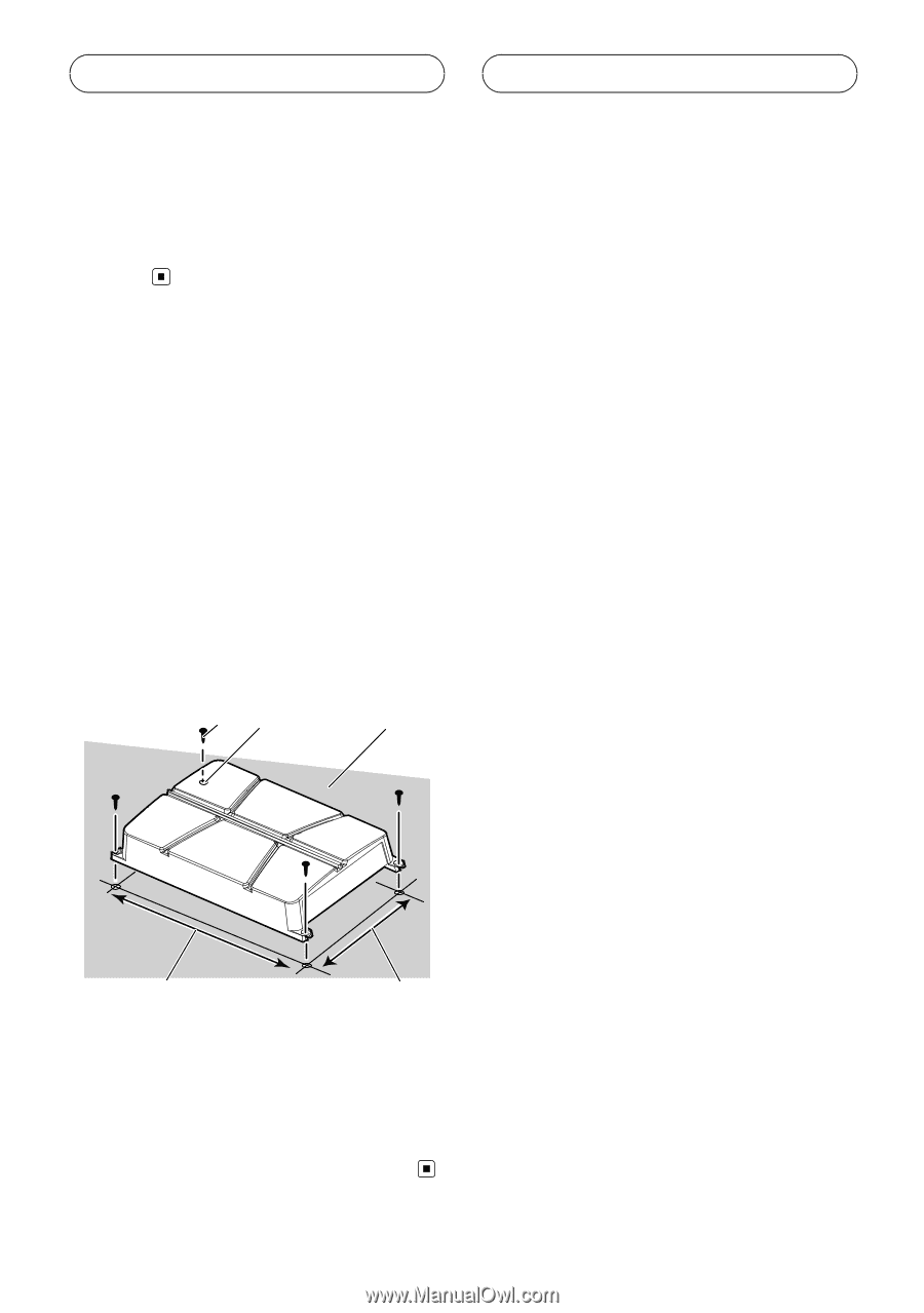
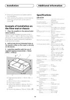
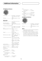
Installation Additional information ! Check all connections and systems before final installation. ! After installing the amplifier, confirm that the spare tire, jack and tools can be easily removed. Example of installation on the floor mat or chassis 1 Place the amplifier in the desired installation location. Insert the supplied tapping screws (4 mm × 18 mm (1/8 in. × 3/4 in.)) into the screw holes and push on the screws with a screwdriver so they make an imprint where the installation holes are to be located. 2 Drill 2.5 mm (1/8 in.) diameter holes at the imprints either on the carpet or directly on the chassis. 3 Install the amplifier with the use of supplied tapping screws (4 mm × 18 mm (1/8 in. × 3/4 in.)). 12 3 4 5 1 Tapping-screws (4 mm × 18 mm (1/8 in. × 3/4 in.)) 2 Drill a 2.5 mm (1/8 in.) diameter hole. 3 Floor mat or chassis 4 Hole-to-hole distance: 343 mm (13-1/2 in.) (GM-A6704) / 313 mm (12-3/8 in.) (GM- A4704) 5 Hole-to-hole distance: 195 mm (7-5/8 in.) Specifications GM-A6704 Power source 14.4 V DC (10.8 V to 15.1 V allowable) Grounding system Negative type Current consumption 31 A (at continuous power, 4 W) Average current consumption 8.5 A (4 W for four channels) 14 A (4 W for two channels) Fuse 25 A × 2 Dimensions (W × H × D) ... 356 mm × 60 mm × 215 mm (14 in. × 2-3/8 in. × 8-1/2 in.) Weight 2.2 kg (4.9 lbs) (Leads for wiring not included) Maximum power output ....... 170 W × 4 (4 W) / 250 W × 4 (2 W) / 1000 W TOTAL (BRIDGE) Continuous power output ... 60 W × 4 (at 14.4 V, 4 W, 20 Hz to 20 kHz ≦ 1 % THD +N) 190 W × 2 (at 14.4 V, 4 W BRIDGE 1 kHz, ≦ 1 % THD +N) 95 W × 4 (at 14.4 V, 2 W, 1 kHz, ≦ 1 % THD+N) Load impedance 4 W (2 W to 8 W allowable) Frequency response 10 Hz to 70 kHz (+0 dB, -3 dB) Signal-to-noise ratio 95 dB (IHF-A network) Distortion 0.05 % (10 W, 1 kHz) Low pass filter: (A ch) Cut off frequency 80 Hz Cut off slope 12 dB/oct (B ch) Cut off frequency 80 Hz Cut off slope 12 dB/oct High pass filter: (A ch) Cut off frequency 40 Hz to 500 Hz Cut off slope 12 dB/oct (B ch) Cut off frequency 80 Hz Cut off slope 12 dB/oct Bass boost: Frequency 50 Hz Level 0 dB/6 dB/12 dB Gain control: RCA 0.3 V to 6.5 V Speaker 3.0 V to 26 V Maximum input level / impedance: RCA 6.5 V / 22 kW Speaker 26 V / 16 kW En
-
 1
1 -
2
-
3
-
4
-
5
-
6
-
7
-
8
-
9
-
 10
10 -
 11
11 -
 12
12 -
 13
13 -
 14
14 -
 15
15 -
 16
16 -
 17
17 -
 18
18 -
 19
19 -
 20
20 -
21
-
22
-
23
-
24
-
25
-
26
-
27
-
28
-
29
-
30
-
31
-
32
 |
 |