Pioneer GM-X364 Owner's Manual - Page 3
Connecting the Unit
 |
View all Pioneer GM-X364 manuals
Add to My Manuals
Save this manual to your list of manuals |
Page 3 highlights
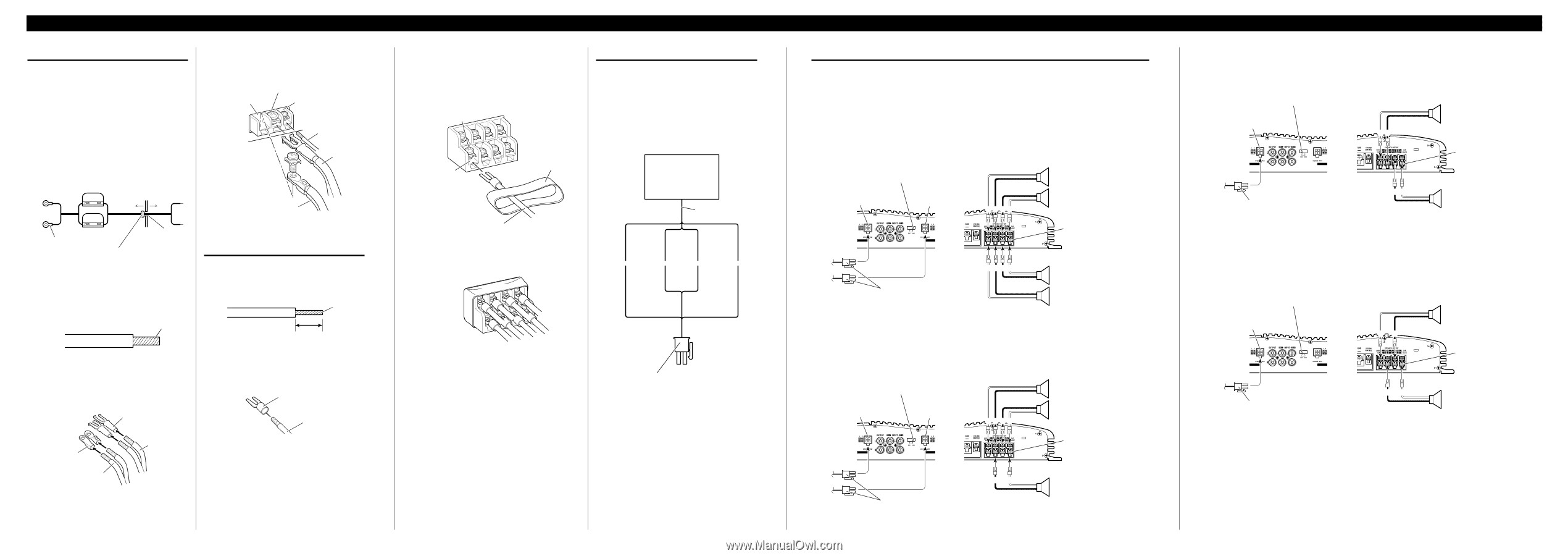
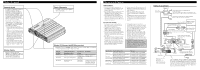
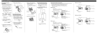
Connecting the Unit Connecting the Power Terminal • Always use the special red battery and ground wire [RD-223], which is sold separately. Connect the battery wire directly to the car battery positive terminal (+) and the ground wire to the car body. 1. Pass the battery wire from the engine compartment to the interior of the vehicle. • After making all other connections to the amplifier, connect the battery wire terminal of the amplifier to the positive (+) terminal of the battery. Engine Fuse (30 A) compart- Interior of ment the vehicle 4. Connect the wires to the terminal. • Fix the wires securely with the terminal screws. GND terminal Power terminal System remote control terminal System remote control wire Ground wire Battery wire Fuse (30 A) Positive terminal Drill a 14 mm (1/2 inch) hole Insert the O-ring rubber into the vehicle grommet into the vehicle body. body. 2. Twist the battery wire, ground wire and system remote control wire. Twist 3. Attach lugs to wire ends. Lugs not supplied. • Use pliers, etc., to crimp lugs to wires. Lug Connecting the Speaker Output Terminals 1. Expose the end of the speaker wires using nippers or a cutter by about 10 mm (3/8 inch) and twist. Twist 10 mm (3/8 inch) 2. Attach lugs to speaker wire ends. Lugs not supplied. • Use pliers, etc., to crimp lugs to wires. Lug Speaker wire Lug Battery wire Ground wire 3. Connect the speaker wires to the speaker output terminals. • Connect the speaker wires, passing them through the terminal cover. • Fix the speaker wires securely with the terminal screws. Terminal screw Using the Speaker Input Connect the car stereo speaker output wires to the amplifier using the supplied speaker input connector. • Do not connect both the RCA input and the speaker input at the same time. 7 Connections when using the speaker input Speaker output terminal Terminal cover Speaker wire Car Stereo Speaker output 4. Push on the terminal cover. White/black: Left ≠ White: Left + Gray/black: Right ≠ Gray: Right + Speaker input connector To speaker input terminal of this unit. Connecting the Speaker wires The speaker output mode can be four-channel, three-channel (stereo + mono) or two-channel (stereo, mono). Connect the speaker leads to suit the mode according to the figures shown below. • When either the RCA input or the speaker input is connected, RCA output becomes functional. Do not connect both the RCA input and the speaker input at the same time. Four-channel mode Input Select Switch For two-channel input, slide this switch to the left. For four-channel input, slide this switch to the right. Speaker input terminal A Speaker input terminal B (Left) Speaker out A (Right) Speaker output terminal Speaker input connector (Right) Speaker out B (Left) Three-channel mode Input Select Switch For two-channel input, slide this switch to the left. For four-channel input, slide this switch to the right. Speaker input terminal A Speaker input terminal B Speaker input connector (Left) Speaker out A (Right) Speaker output terminal Speaker out B (Mono) Two-channel mode (stereo) Input Select Switch Slide this switch to the left. Speaker input terminal A Speaker input connector Two-channel mode (mono) Input Select Switch Slide this switch to the left. Speaker input terminal A Speaker input connector +≠ ≠+ +≠ ≠+ Speaker (Left) Speaker output terminal Speaker (Right) Speaker (Mono) Speaker output terminal Speaker (Mono)
-
 1
1 -
 2
2 -
 3
3 -
 4
4 -
 5
5 -
 6
6 -
 7
7 -
 8
8
 |
 |