Pioneer GM-X424 Service Manual
Pioneer GM-X424 Manual
 |
View all Pioneer GM-X424 manuals
Add to My Manuals
Save this manual to your list of manuals |
Pioneer GM-X424 manual content summary:
- Pioneer GM-X424 | Service Manual - Page 1
Service Manual ORDER NO. CRT2168 BRIDGEABLE FOUR-CHANNEL POWER AMPLIFIER GM-X424 X1R/UC, ES, EW GM-X324 X1R/UC CONTENTS 1. SAFETY INFORMATION 1 2. EXPLODED VIEWS AND PARTS LIST 2 3. SCHEMATIC DIAGRAM 6 4. PCB CONNECTION DIAGRAM 8 1. SAFETY INFORMATION 5. ELECTRICAL PARTS LIST 12 6. - Pioneer GM-X424 | Service Manual - Page 2
GM-X424, GM-X324 2. EXPLODED VIEWS AND PARTS LIST 2.1 PACKING Fig. 1 NOTE: - Parts marked by Mark No. Description 6 Polyethylene Bag 7 Terminal(x8) 8 Cord Assy 9-1 Owner's Manual 9-2 Owner's Manual Part No. HEG0011 See Contrast table (2) See Contrast table (2) See Contrast table (2) - Pioneer GM-X424 | Service Manual - Page 3
used Not used Not used HRY1087 Not used Not used Not used Not used Not used ARY1048 - Owner's Manual Model GM-X424/X1R/UC GM-X424/X1R/ES GM-X424/X1R/EW GM-X324/X1R/UC Part No. HRD0052 HRD0050 HRD0053 HRD0055 HRD0054 Language English, French English, Spanish Arabic, Portuguese(B) English, French - Pioneer GM-X424 | Service Manual - Page 4
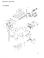
GM-X424, GM-X324 2.2 EXTERIOR Fig. 2 4 - Pioneer GM-X424 | Service Manual - Page 5
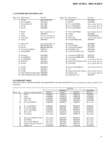
-X424/X1R/UC, GM-X424/X1R/ES, GM-X424/X1R/EW and GM-X324/X1R/UC are constructed the same except for the following: Mark No. 6 8 9 11 28 Symbol and Description Panel Panel Heat Sink Amp Unit Pin Jack(CN852) X1R/UC HNB0053 HNB0048 HNR0091 HWH0054 HKB0002 Part No. GM-X424 X1R/ES X1R/EW HNB0071 - Pioneer GM-X424 | Service Manual - Page 6
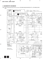
: When ordering service parts, be sure to refer to "EXPLODED VIEWS AND PARTS LIST" or "ELECTRICAL PARTS LIST". THRU-PUT A MOTHER PCB GM-X424 only A Lch B ISOLATOR PCB LPF / HPF R179, 180 : GM-X324 only VR153 : GM-X424 only BASS B A Rch ISOLATOR B Lch C ISOLATOR B Rch AMP UNIT Consists - Pioneer GM-X424 | Service Manual - Page 7
5 6 7 8 GM-X424, GM-X324 A BASS BOOST 4R7/50 BUFFER AMP PRE DRIVER POWER AMP OVER CURRENT DETECTOR OVER VOLTAGE DETECTOR 4R7/50 B FLAT AMP FLAT AMP MUTE MUTE POWER CONTROL / MUTE 22/50 R VOLTAGE TETECTOR 5 6 POWER DETECTOR C OVER CURRENT PROTECTOR & OVER VOLTAGE PROTECTOR ES - Pioneer GM-X424 | Service Manual - Page 8
1 2 3 GM-X424, GM-X324 4. PCB CONNECTION DIAGRAM A NOTE FOR PCB DIAGRAMS 1. The parts mounted on this PCB 2. Viewpoint of PCB diagrams include all necessary parts for several destination. For - Pioneer GM-X424 | Service Manual - Page 9
5 6 G G G G 5 6 7 8 GM-X424, GM-X324 A SIDE A CN601 1 2 3 4 5 B CORD ASSY C B CN861, CN862 OUT IN D Fig. 4 A9 7 8 - Pioneer GM-X424 | Service Manual - Page 10
1 2 3 4 GM-X424, GM-X324 A A MOTHER PCB B C D A 10 1 2 3 4 - Pioneer GM-X424 | Service Manual - Page 11
5 6 7 8 GM-X424, GM-X324 A SIDE B B ISOLATOR PCB B C D Fig. 5 A B 11 5 6 7 8 - Pioneer GM-X424 | Service Manual - Page 12
GM-X424, GM-X324 5. ELECTRICAL PARTS LIST NOTE: - Parts whose parts numbers are omitted CSZS..... =====Circuit Symbol and No.===Part Name GM-X424/X1R/UC Part No AMP UNIT Consists of MOTHER PCB ISOLATOR PCB A B Unit Number : HWH0054 Unit Name : Amp Unit MISCELLANEOUS IC 121 IC IC 122 IC - Pioneer GM-X424 | Service Manual - Page 13
GM-X424, GM-X324 =====Circuit Symbol and No.===Part Name S 101 S 102 S 851 VR 151 VR 153 Switch Switch Switch Volume 10kΩ(C) Volume 50kΩ(C) VR 201 VR 202 FU - Pioneer GM-X424 | Service Manual - Page 14
GM-X424, GM-X324 =====Circuit Symbol and No.===Part Name R 378 0.22Ω R 379 0.22Ω R 380 0.22Ω R 381 0.22Ω R 382 0.22Ω R 383 0.22Ω R 384 0.22Ω R 385 0.22Ω R 386 0.22Ω R 387 0. - Pioneer GM-X424 | Service Manual - Page 15
CCSSL101J50 CCSSL101J50 CCSSL101J50 CCSSL101J50 CCH1036 GM-X424/X1R/UC, GM-X424/X1R/ES, GM-X424/X1R/EW and GM-X324/X1R/UC are constructed the same except for the following: - Amp Unit Part No. Symbol and Description GM-X424/X1R/UC GM-X424/X1R/ES GM-X424/X1R/EW GM-X324/X1R/UC S601 Switch Not - Pioneer GM-X424 | Service Manual - Page 16
GM-X424, GM-X324 6. ADJUSTMENT There is no information to be shown in this chapter. 7. GENERAL INFORMATION 7.1 DISASSEMBLY A - Removing the Case and Panel 1. Remove six screws A, and then remove case. 2. Remove panel. A Panel B Sub Heat Sink C Amp Unit 16 Case Fig. 6 D C B - Removing the Amp - Pioneer GM-X424 | Service Manual - Page 17
. • Set the gain control to "NORMAL" when this amplifier is connected to a Pioneer car stereo with RCA output jacks. If the sound is too is not necessary for the speaker you use. Power Indicator The power indicator lights when the power is switched on. BFC (Beat Frequency Control) GM-X424, GM-X324 - Pioneer GM-X424 | Service Manual - Page 18
GM-X424, GM-X324 18 - CONNECTION DIAGRAM (1) GM-X424/X1R/UC Grommet Fuse (30 A) Special red battery wire [RD-222] (sold separately). After making all other connections at the amplifier, connect the battery wire terminal of the amplifier to the positive (+) terminal of the battery. Ground wire - Pioneer GM-X424 | Service Manual - Page 19
GM-X424, GM-X324 19 (3) GM-X324/X1R/UC Grommet Fuse (30 A) Fuse (25 A) Speaker output terminal See the "Connecting the Speakers and Input wires" section for speaker connection instructions. Special red battery wire [RD-222] (sold separately). After making all other connections at the amplifier, - Pioneer GM-X424 | Service Manual - Page 20
GM-X424, GM-X324 20 - CONNECTING THE SPEAKERS AND INPUT WIRES The speaker output mode can be four-channel, three-channel (stereo + mono) or two-channel (stereo, mono). Connect - Pioneer GM-X424 | Service Manual - Page 21
2-1/8 (H) × 10-5/8 (D) in.] Weight ...3.2 kg (7.1 lbs.) (Leads for wiring not included) Maximum power output ...60 W × 4 / 140 W × 2 (EIAJ) Continuous power output (UC and ES models 30 W × 4 (at 14.4V, 4 Ω, 20 - 20,000 out total current drawn by multiple power amplifiers. GM-X424, GM-X324 21
-
 1
1 -
 2
2 -
 3
3 -
 4
4 -
 5
5 -
 6
6 -
 7
7 -
8
-
9
-
10
-
11
-
12
-
13
-
14
-
15
-
16
-
17
-
18
-
19
-
20
-
21
 |
 |

ORDER NO.
CRT2168
S
e
r
v
i
c
e
M
a
nu
a
l
BRIDGEABLE FOUR-CHANNEL POWER AMPLIFIER
PIONEER ELECTRONIC CORPORATION
4-1, Meguro 1-Chome, Meguro-ku, Tokyo 153-8654, Japan
PIONEER ELECTRONICS SERVICE INC.
P.O.Box 1760, Long Beach, CA 90801-1760 U.S.A.
PIONEER ELECTRONIC [EUROPE] N.V.
Haven 1087 Keetberglaan 1, 9120 Melsele, Belgium
PIONEER ELECTRONICS ASIACENTRE, PTE.LTD.
501 Orchard Road, #10-00, Wheelock Place, Singapore 238880
C
PIONEER ELECTRONIC CORPORATION 1998
K-ZEU. JAN. 1998 Printed in Japan
GM-X424
X1R/UC, ES, EW
CONTENTS
1. SAFETY INFORMATION
............................................
1
2. EXPLODED VIEWS AND PARTS LIST
.......................
2
3. SCHEMATIC DIAGRAM
.............................................
6
4. PCB CONNECTION DIAGRAM
..................................
8
5. ELECTRICAL PARTS LIST
........................................
12
6. ADJUSTMENT
..........................................................
16
7. GENERAL INFORMATION
.......................................
16
7.1 DISASSEMBLY
...................................................
16
8. OPERATIONS AND SPECIFICATIONS
.....................
17
1. SAFETY INFORMATION
This service manual is intended for qualified service technicians; it is not meant for the casual do-it-yourselfer.
Qualified technicians have the necessary test equipment and tools, and have been trained to properly and safely repair
complex products such as those covered by this manual.
Improperly performed repairs can adversely affect the safety and reliability of the product and may void the warranty.
If you are not qualified to perform the repair of this product properly and safely, you should mot risk trying to do so
and refer the repair to a qualified service technician.
UC model
CAUTION
This service manual is intended for qualified service technicians; it is not meant for the casual do-it-yourselfer.
Qualified technicians have the necessary test equipment and tools, and have been trained to properly and safely repair
complex products such as those covered by this manual.
Improperly performed repairs can adversely affect the safety and reliability of the product and may void the warranty.
If you are not qualified to perform the repair of this product properly and safely; you should not risk trying to do so
and refer the repair to a qualified service technician.
W
ARNING
Lead in solder used in this product is listed by the California Health and Welfare agency as a known reproductive toxi-
cant which may cause birth defects or other reproductive harm (California Health & Safety Code, Section 25249.5).
When servicing or handling circuit boards and other components which contain lead in solder, avoid unprotected skin
contact with the solder. Also, when soldering do not inhale any smoke or fumes produced.
GM-X324
X1R/UC