Pioneer GM-X424 Service Manual - Page 16
General Information, Adjustment
 |
View all Pioneer GM-X424 manuals
Add to My Manuals
Save this manual to your list of manuals |
Page 16 highlights
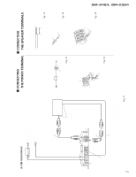
GM-X424, GM-X324 6. ADJUSTMENT There is no information to be shown in this chapter. 7. GENERAL INFORMATION 7.1 DISASSEMBLY A - Removing the Case and Panel 1. Remove six screws A, and then remove case. 2. Remove panel. A Panel B Sub Heat Sink C Amp Unit 16 Case Fig. 6 D C B - Removing the Amp Unit Some silicone glue has been applied between the Heat Sink and the Sub Heat Sink. therefore, to remove the Amp Unit from the Heat Sink. Panel C 1. Remove two screws D. 2. Remove Panel. 3. Remove six screws B and five screws C. 4. Use 2 pcs. of screw B and insert them into the two holes marked with an arrow. 5. Alternately tighten them little by little until the Sub Heat Sink separates from the Heat Sink. Sub Heat Sink Heat Sink Fig. 7
-
 1
1 -
2
-
3
-
4
-
5
-
6
-
7
-
8
-
9
-
10
-
 11
11 -
 12
12 -
 13
13 -
 14
14 -
 15
15 -
 16
16 -
 17
17 -
 18
18 -
 19
19 -
 20
20 -
 21
21
 |
 |

B
C
D
B
C
C
A
A
16
GM-X424, GM-X324
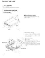
7. GENERAL INFORMATION
7.1 DISASSEMBLY
-
Removing the Case and Panel
1. Remove six screws A, and then remove case.
2. Remove panel.
Panel
Case
Sub Heat Sink
Sub Heat Sink
Heat Sink
Amp Unit
Panel
-
Removing the Amp Unit
Some silicone glue has been applied
between the Heat Sink and the Sub Heat
Sink. therefore, to remove the Amp Unit
from the Heat Sink.
1. Remove two screws D.
2. Remove Panel.
3. Remove six screws B and five screws C.
4. Use 2 pcs. of screw B and insert them into
the two holes marked with an arrow.
5. Alternately tighten them little by little until
the Sub Heat Sink separates from the Heat
Sink.
6. ADJUSTMENT
There is no information to be shown in this chapter.
Fig. 6
Fig. 7