Pioneer ND-BC20PA Owner's Manual - Page 3
Display and Actual Road Surfac - video
 |
UPC - 012562867762
View all Pioneer ND-BC20PA manuals
Add to My Manuals
Save this manual to your list of manuals |
Page 3 highlights
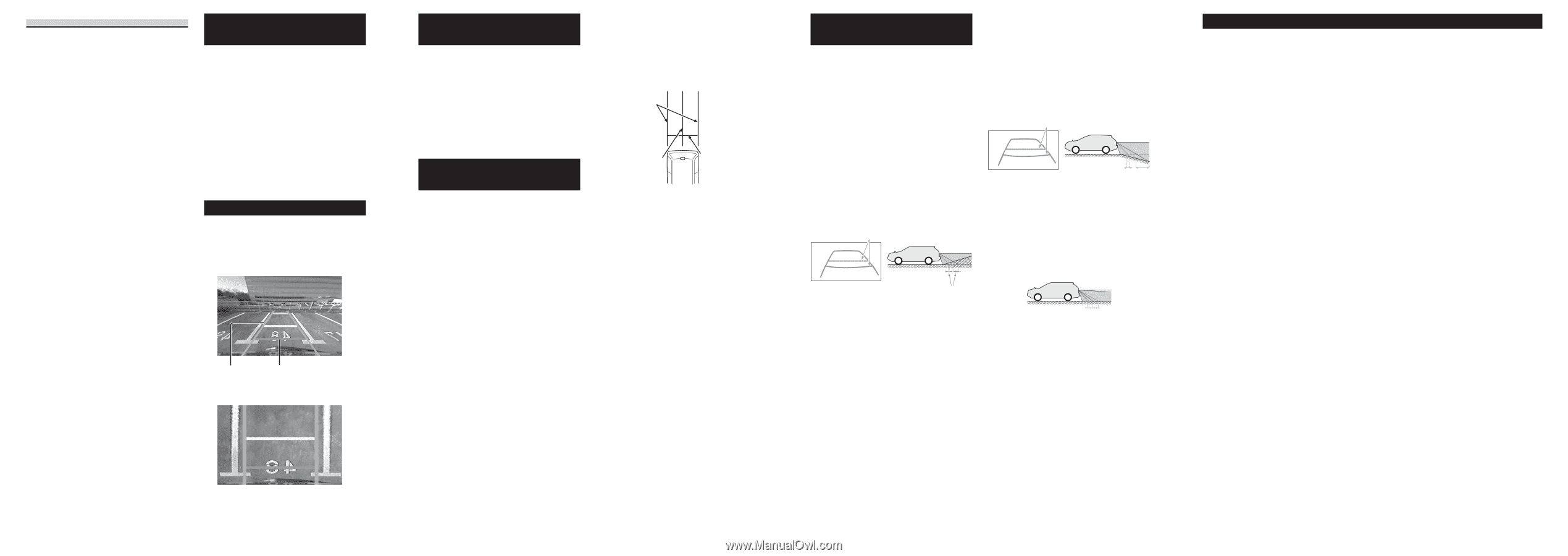
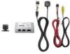
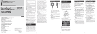
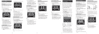
D. Guideline (On/Off) This is used to switch the vertical and horizontal guidelines on and off. 1. Press the ENTER button. 2. Select on or off for the guidelines with the + and - buttons. 3. Press the ENTER button. 4. Press the ENTER button twice. Return to step 5 of "Changing Basic Settings or Other Settings". Returning to Default Settings The product can be reset to the default settings. Reset to default settings in the following situations: • The position of the camera has changed. • The vehicle on which the camera is installed has changed. 1. Press the MODE and ENTER buttons simultaneously. Note: • Press the MODE button to cancel resetting to default settings. 2. Press the ENTER button. All of the settings are returned to the default settings. Screen Display Two types of screen displays are available with this product. Normal Angle Mode: This is used when displaying the normal rear view camera image. Vertical guidelines Horizontal guidelines High Angle Mode: This displays the view from directly overhead. Changing the Screen Display Mode 1. Press the MODE button when the rear view camera image is displayed. The screen display mode changes in the manner described below each time the MODE button is pressed. Normal angle mode ↔ High angle mode Note: • The screen display mode returns to the normal angle mode prior to being changed when the engine is turned off. Optional Advanced Setup Preparation To improve accuracy, the optional setup will use a grid of masking tape to provide a visual representation similar to the on-screen setting of the system. To complete this procedure, you will need approximately 54 feet (18 yards) (16.5 meter) of 2 inch (5 centimeter) wide masking tape (or wider). Please see the image below and follow these steps to complete the procedure: 1) Cut one strip of masking tape equal to the width of the vehicle. Place the masking tape on the parking surface approximately 3 feet (1 meter) from and parallel to the rear bumper. This strip of masking tape will be the indicator used to adjust the RED line in Advanced Settings - Step C. Guideline (Distance). 2) Cut two strips of masking tape, approximately 15 feet (4.5 meter) in length, and place them on the parking surface in the position shown in the image below, parallel to the sides of the vehicle and extending to the rear. These strips represent the width of the vehicle, and will be used instead of the painted parking lines in both the Basic Settings and Advanced Settings. 3) Cut one strip of masking tape, approximately 15 feet (4.5 meter) in length, and place on the parking surface from the center of the rear bumper extending back. This strip will indicate the centerline of the vehicle and will be used in both the Basic Settings and Advanced Settings. Step 2 Step 3 Step 1 Discrepancies Between Screen Display and Actual Road Surface Discrepancies in distance and the course over which the vehicle is traveling may occur between the horizontal guidelines on the screen and actual road surface in the following situations. When there is a steep upgrade behind the vehicle: The horizontal guidelines serve as a reference for distance relative to a flat road surface. Consequently, when there is a steep upgrade behind the vehicle, the horizontal guidelines appear closer to you than the actual distances. For example, in the case of an obstacle present on a steep upgrade, the obstacle appears to be farther away than it actually is. Similarly, discrepancies also occur in the course over which the vehicle is traveling between the horizontal guidelines and the actual road surface. ➀ ➁ ➂ ➀ Horizontal guidelines ➁ Vehicle status ➂ Discrepancy When there is a steep downgrade behind the vehicle: When there is a steep downgrade behind the vehicle, the horizontal guidelines appear farther to the rear than the actual distances. When there is an obstacle present on a steep downgrade, the obstacle appears to be closer than it actually is. Similarly, discrepancies also occur in the course over which the vehicle is traveling between the horizontal guidelines and the actual road surface. ➀ ➁ ➂ ➀ Horizontal guidelines ➁ Vehicle status ➂ Discrepancy When the vehicle is on an incline: Discrepancies may occur between the display and the actual distance and course over which the vehicle is traveling when the vehicle is on an incline due to the number of passengers or payload. ➀ ➁ ➀ Vehicle status ➁ Discrepancy Specifications Common Units Power source DC 14.4 V (allowable range: 10.8 V to 15.1 V) Grounding system Negative ground type Max. current consumption Approx. 250 mA Output image Mirror image (for rear view confirmation) Video output 1 Vp-p (75 Ω) External Dimensions Rear view camera 27 (W) × 27 (H) × 26 (D) mm 1 (W) × 1 (H) × 1 (D) in. Image processing unit power supply 84 (W) × 20 (H) × 65 (D) mm 3-1/4 (W) × 3/4 (H) × 2-1/2 (D) in. Button unit 27 (W) × 27 (H) × 13 (D) mm 1 (W) × 1 (H) × 1/2 (D) in. Weights Rear view camera 150 g (0.3 lbs) (including cable) Image processing unit power supply 200 g (0.44 lbs) (including power cord) Button unit 95 g (0.2 lbs) (including cable) Camera Unit Imaging sensor 1/4-inch color CCD sensor No. of pixels 492 (vertical) × 512 (horizontal) (total no. of pixels: approx. 270 000, effective no. of pixels: approx. 250 000) Lens Wide-angle, focal length: 1.53 mm, F value: 2.8 Angle of view Horizontal: approx. 135˚, vertical: approx. 100˚ IR cutoff (special vehicle-mounted) filter Provided Iris system Electronic iris Scanning system Interlace Synchronizing system Internal synchronization Signal-to-noise ratio 40 dB or more Horizontal resolution Approx. 300 TV lines Illumination range Approx. 1.5 lux to 100 000 lux Operating temperature range 30 ˚C to +70 ˚C −22 ˚F to +158 ˚F Storage temperature range 40 ˚C to +85 ˚C −40 ˚F to +185 ˚F Note: • Specifications and the design are subject to possible modification without prior notice due to improvements. En En En En
-
 1
1 -
 2
2 -
 3
3 -
 4
4 -
 5
5 -
 6
6
 |
 |