Pioneer VSX-816-K Service Manual - Page 134
Troubleshooting, 3 V Regulator IC input
 |
UPC - 012562785851
View all Pioneer VSX-816-K manuals
Add to My Manuals
Save this manual to your list of manuals |
Page 134 highlights
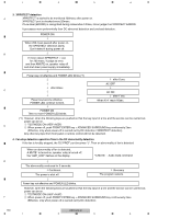
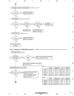
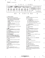
1 2 7.3.4.3 Troubleshooting Step 1: Connectors A CN701, CN702 Are the connectors securely inserted ? Yes To STEP 2 No Insert the connectors securely. Step 2: Power supply B 1 CN702 (pin 4) 5 V input Is No the voltage 5 V ? Yes Is there any loose No connection of CN702? Yes Check the MOTHER Assy. 2 C IC703 (pin 3) To STEP 1 3.3 V Regulator IC input Is the voltage 5 V ? No Check the patterns in the path. Yes 3 IC951 (pin 14) 3-5 Converter D 4 Is the voltage 5 V ? No Check the parts and patterns in the path. Yes IC771 (pin 5) USB Power SW Is the voltage 5 V ? No Check the parts and patterns in the path. Yes E 5 IC7814 (pins 14, 15) DAC Is the voltage 5 V ? Yes No Check the parts and patterns in the path. 3 4 6 IC703 (pin 1), IC702 (pin 7) 3.3 V Reg. output / 1.8 V Reg. input Is the voltage No 3.3 V ? Yes Is IC703 abnormally hot? Yes No Replace IC703. The output and GND may be short-circuited. Check the path between them. 7 IC762 (pins 37, 47) FLASH ROM Is the voltage 3.3 V ? Yes No Check the parts and patterns in the path. 8 IC761 (pins 1,3,9,14,27,43,49) SDRAM Is the voltage 3.3 V ? Yes No Check the parts and patterns in the path. 9 IC953 (pin 14) 5-3 Converter Is the voltage 3.3 V ? Yes No Check the parts and patterns in the path. 10 IC701 (pins 16,33,64,76,112) USB Media control IC Is the voltage 3.3 V ? Yes No Check the parts and patterns in the path. 11 IC702 (pin 1) 1.8 V Regulator output Is the voltage 1.8 V ? Yes No Is IC702 No abnormally hot? Yes Replace IC702. The output and GND may be short-circuited. Check the path between them. A F 134 VSX-816-K 1 2 3 4
-
 1
1 -
2
-
3
-
4
-
5
-
6
-
7
-
8
-
9
-
10
-
11
-
12
-
13
-
14
-
15
-
16
-
17
-
18
-
19
-
20
-
21
-
22
-
23
-
24
-
25
-
26
-
27
-
28
-
29
-
30
-
31
-
32
-
33
-
34
-
35
-
36
-
37
-
38
-
39
-
40
-
41
-
42
-
43
-
44
-
45
-
46
-
47
-
48
-
49
-
50
-
51
-
52
-
53
-
54
-
55
-
56
-
57
-
58
-
59
-
60
-
61
-
62
-
63
-
64
-
65
-
66
-
67
-
68
-
69
-
70
-
71
-
72
-
73
-
74
-
75
-
76
-
77
-
78
-
79
-
80
-
81
-
82
-
83
-
84
-
85
-
86
-
87
-
88
-
89
-
90
-
91
-
92
-
93
-
94
-
95
-
96
-
97
-
98
-
99
-
100
-
101
-
102
-
103
-
104
-
105
-
106
-
107
-
108
-
109
-
110
-
111
-
112
-
113
-
114
-
115
-
116
-
117
-
118
-
119
-
120
-
121
-
122
-
123
-
124
-
125
-
126
-
127
-
128
-
 129
129 -
 130
130 -
 131
131 -
 132
132 -
 133
133 -
 134
134 -
 135
135 -
 136
136 -
 137
137 -
 138
138 -
 139
139 -
140
-
141
-
142
-
143
-
144
 |
 |
