Polaroid FLM-1514B User Manual - Page 7
Rear Panel - tv
 |
UPC - 826219006325
View all Polaroid FLM-1514B manuals
Add to My Manuals
Save this manual to your list of manuals |
Page 7 highlights
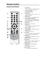
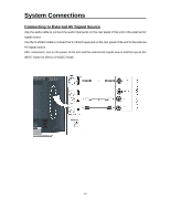
Rear Panel 1. Component Input / L/R Audio Input Jack Connected to the Component (YPbPr) input in Component mode. Connected to the L/R audio input in Component mode. 2. S-VIDEO Input Jacks 3. VIDEO/L/R Audio Input Jack Connected to the VIDEO input in Composite mode. Connected to the L/R audio input in Composite mode. 4. DC 9.5V/12V In Jack Connected to power adapter. 5. VGA Input Jack Connected to the VGA output jack on a personal computer. 6. PC AUDIO Input Jack Connected to the PC audio output jack. 7. TV Signal Input Jack Connected for the external NTSC TV signal input. - 6 -
-
 1
1 -
 2
2 -
 3
3 -
 4
4 -
 5
5 -
 6
6 -
 7
7 -
 8
8 -
 9
9 -
 10
10 -
 11
11 -
 12
12 -
13
-
14
-
15
-
16
-
17
-
18
-
19
-
20
-
21
-
22
-
23
-
24
-
25
-
26
-
27
-
28
 |
 |

- 6 -
Rear Panel
1.
Component Input / L/R Audio Input Jack
Connected to the Component (YPbPr) input
in Component mode.
Connected to the L/R audio input in
Component mode.
2. S-VIDEO Input Jacks
3.
VIDEO/L/R Audio Input Jack
Connected
to
the
VIDEO
input
in
Composite mode.
Connected to the L/R audio input in
Composite mode.
4. DC 9.5V/12V In Jack
Connected to power adapter.
5. VGA Input Jack
Connected to the VGA output jack on a
personal computer.
6.
PC AUDIO Input Jack
Connected to the PC audio output jack.
7. TV Signal Input Jack
Connected for the external NTSC TV
signal input.