Polaroid FLM-3201 Service Manual
Polaroid FLM-3201 - 32" LCD TV Manual
 |
View all Polaroid FLM-3201 manuals
Add to My Manuals
Save this manual to your list of manuals |
Polaroid FLM-3201 manual content summary:
- Polaroid FLM-3201 | Service Manual - Page 1
32" LCD Television FLM-3201 32" LCD Television FLM-3201 Service Manual 20051205 - Polaroid FLM-3201 | Service Manual - Page 2
Tech Support line at 1-866-396-6322 Model FLM-3201 Part Number 667-L32K5-05 667-L32K5-09 667-L32K5-16 667-L32K5N-40 667-L32K5N-56 667-L34K5-20 301-DL26K7-01A 615-10464-06 Description Keypress Board IR Receive Board USB Board Audio/Video Processing Board CPU Board Power Supply Board KAS20 Remote - Polaroid FLM-3201 | Service Manual - Page 3
instruction 3 Trouble shooting 5 Method of software upgrading 7 LC-32K5 working principle analysis 9 LC-32K5 block diagram 10 IC block diagram 11 Main assembly 17 Identification criteria for the bright spot and dark spot of the LCD screen 18 Wiring diagram 19 Troubleshooting charts - Polaroid FLM-3201 | Service Manual - Page 4
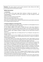
Attention: This service manual is only for service personnel to take reference with. Before servicing please read the following points carefully. Safety instructions 1. Instructions Be sure to switch off the power supply before replacing or welding any components or inserting/plugging in connection - Polaroid FLM-3201 | Service Manual - Page 5
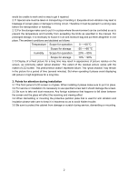
Scope for storage 10% ~ 90% 2.13 Display of a fixed picture for a long time may result in appearance of picture residue on the screen, as commonly called "ghost shadow". The extent of the residual picture varies with the maker of LCD screen. This phenomenon doesn't represent failure. This "ghost - Polaroid FLM-3201 | Service Manual - Page 6
-L32K50-03JL, connect with power and observe the display. Method for entering factory menu: press "VOL+", "MUTE" and "VIDEO" repeatedly to enter factory menu; press "ENTER" to select different items when the first line of each adjustment item just lights up; input VGA and DVI signal, then select the - Polaroid FLM-3201 | Service Manual - Page 7
", shut down the unit after "ok" appears. 3.2 VGA/DVI channel adjustment 3.2.1 Preset VGA channel mode Input VGA signal (PATTERN 5: Final Test) of K-7253, select TIME301(640*350/70Hz), press "AUTO" to do the auto adjustment until the screen is filled with picture. Use the same method to do auto - Polaroid FLM-3201 | Service Manual - Page 8
before ex-factory item Picture mode Sound mode setting NATURE NEWS N/R SCREEN WEAK 16:9 item OSD language VGA color temperature SPEAKER HEAD PHONE setting English 9300 ON ON item BALANCE SRS CCD Turn off setting 50 OFF OFF TV Trouble shooting Before servicing please check to find - Polaroid FLM-3201 | Service Manual - Page 9
to the wrong terminal or if the input mode is correct. Check if the signal cable connection between video frequency source and the liquid crystal TV set is correct. Check if all the picture setups have been corrected. Check is the screen position and size is correctly set up. Check to see if the - Polaroid FLM-3201 | Service Manual - Page 10
is not connected. Check if the cable connection is loose. When being played or in pause VHS picture search tape sometimes can't provide stable picture, which may lead to incorrect display of the liquid crystal TV, In this case please press "auto" key on the remote control so as to enable the liquid - Polaroid FLM-3201 | Service Manual - Page 11
change to another port). Baud is selected to be 115200. Then select Reset Target After Download. Click FLASH pushbutton, it's ready to run. For flash. Then shut the main power supply and it's OK just switch it on again. Note: Do not shut the power off or turn the TV set on during the FLASH write - Polaroid FLM-3201 | Service Manual - Page 12
composite color television signal video signal, part of the selected video LCD screen to do the picture display PWM of U12 can also be used to control the brightness of back light-source. Send SIF (the second IF) outputted by tuner to audio processor N201 MSP3420; send YPRPB and audio signal of DVI - Polaroid FLM-3201 | Service Manual - Page 13
- Polaroid FLM-3201 | Service Manual - Page 14
IC block diagram 1.MSP3420 Pins description: 2,3 PIN: SCL,SDA applied for control the operation of IC . 27,28 PIN: output left and right sound channel R/L to speaker processor. 36,37 PIN:AV OUT of VGA. R/L 53,54 PIN:Input of AV1/SVHS and AV2 R/L. 56,57 PIN:Input R/L of BS 67 PIN: Input TV SIF. 11 - Polaroid FLM-3201 | Service Manual - Page 15
: Input U of PCMCIA. 5,73 PIN: Input Y of PCMCIA. 6 PIN: Input V of PCMCIA 31-34, 37-40 PIN: output format signal of. ITU-R656 70 PIN:Video of AV OUT 71 PIN:Input C of SVHS. 72 PIN:input Video (SVHS in priority) of Y or AV1 of SVHS. 74 PIN:input - Polaroid FLM-3201 | Service Manual - Page 16
3.AD9883 13 - Polaroid FLM-3201 | Service Manual - Page 17
4.FLI2310-Simplified Internal Block Diagram 14 - Polaroid FLM-3201 | Service Manual - Page 18
5.JAG-ASM 15 - Polaroid FLM-3201 | Service Manual - Page 19
6.Z86229 Pins description: 7 PIN: VDIEO INPUT 2 PIN: G OUTPUT 3 PIN: B OUTPUT 18 PIN: R OUTPUT 17 PIN: FB OUTPUT 16 - Polaroid FLM-3201 | Service Manual - Page 20
- Polaroid FLM-3201 | Service Manual - Page 21
criteria for the bright spot and dark spot of the LCD screen Category criteria 15" Bright spot One single ≤5 spot 2 ): It is identified as a defected point if its area exceeds 1/2 of a single picture element (R,G,B). 2. Definition of bright spot: It is identified as a bright spot if it - Polaroid FLM-3201 | Service Manual - Page 22
To speaker Wiring diagram 19 Power supply board AV processing board CPU board To IR board To Keypad board To earphone - Polaroid FLM-3201 | Service Manual - Page 23
is light in the STANDBY? no Check PIN7(12V output) of the power supply board CN904 Check the indicator in turn-on condition Non-change color no no Check if it's melted of FUSE in the power supply board? no no blue Check if the indicator is flicker in the sensor control normal condition - Polaroid FLM-3201 | Service Manual - Page 24
-menu, operation CLEAR no EEPROM, then turn off , turn on again , it if display picture. yes Adjust CPU board again YPRPB Which is no VGA/DVI signal of channels Replacing CPU board TV Testing power supply (+5V-V) of video processing board Check input 22V no of sound conversion - Polaroid FLM-3201 | Service Manual - Page 25
3.no sound Check if PIN1 is 12V of yes yes N04 and N05 Check PIN5 and PIN8 output of N02 no Check power supply no Check PIN27 and yes PIN28 output wave of N01 no yes Check PIN67 wave of N01 no Replacing N04 and N05 Replacing N02 Replacing N01 Replacing TUNER01 22 - Polaroid FLM-3201 | Service Manual - Page 26
- Polaroid FLM-3201 | Service Manual - Page 27
- Polaroid FLM-3201 | Service Manual - Page 28
- Polaroid FLM-3201 | Service Manual - Page 29
- Polaroid FLM-3201 | Service Manual - Page 30
- Polaroid FLM-3201 | Service Manual - Page 31
- Polaroid FLM-3201 | Service Manual - Page 32
- Polaroid FLM-3201 | Service Manual - Page 33
- Polaroid FLM-3201 | Service Manual - Page 34
- Polaroid FLM-3201 | Service Manual - Page 35
- Polaroid FLM-3201 | Service Manual - Page 36
- Polaroid FLM-3201 | Service Manual - Page 37
- Polaroid FLM-3201 | Service Manual - Page 38
- Polaroid FLM-3201 | Service Manual - Page 39
- Polaroid FLM-3201 | Service Manual - Page 40
- Polaroid FLM-3201 | Service Manual - Page 41
- Polaroid FLM-3201 | Service Manual - Page 42
- Polaroid FLM-3201 | Service Manual - Page 43
- Polaroid FLM-3201 | Service Manual - Page 44
For service, support and warranty information, visit www.pwwservice.com or call 1-866-396-6322. "Polaroid" and "Polaroid and Pixel" are trademarks of Polaroid Corporation, Waltham, MA, USA. PRINTED ON RREECCYYCCLLEEDDPPAAPPEERR 604-L32K56-00
-
 1
1 -
 2
2 -
 3
3 -
 4
4 -
 5
5 -
 6
6 -
 7
7 -
8
-
9
-
10
-
11
-
12
-
13
-
14
-
15
-
16
-
17
-
18
-
19
-
20
-
21
-
22
-
23
-
24
-
25
-
26
-
27
-
28
-
29
-
30
-
31
-
32
-
33
-
34
-
35
-
36
-
37
-
38
-
39
-
40
-
41
-
42
-
43
-
44
 |
 |

FLM-3201
Service Manual
32” LCD Television
20051205