Poulan 1994-06 User Manual - Page 7
Preparing
 |
View all Poulan 1994-06 manuals
Add to My Manuals
Save this manual to your list of manuals |
Page 7 highlights
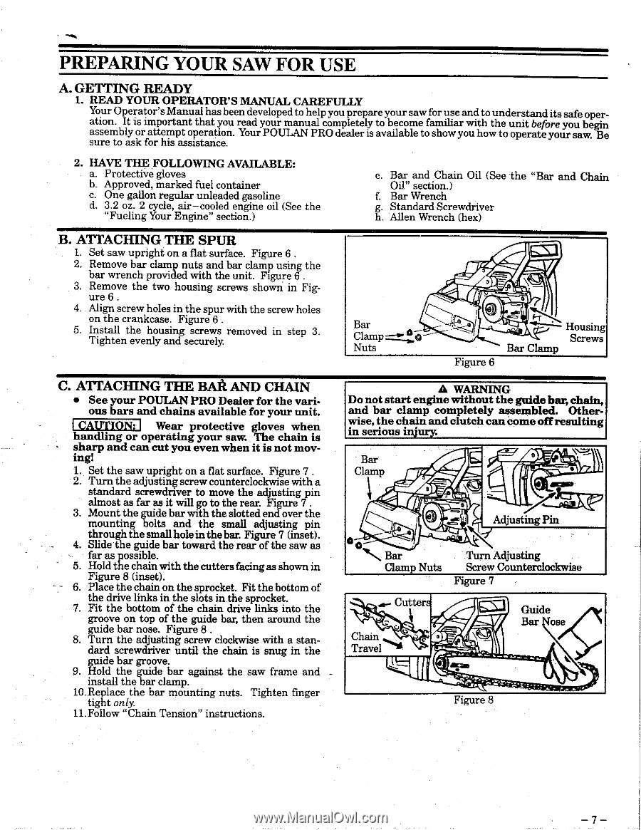
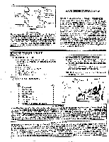
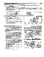
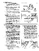
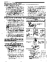
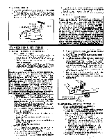
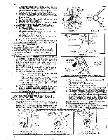
PREPARING YOUR SAW FOR USE A. GETTING READY 1. READ YOUR OPERATOR'S MANUAL CAREFULLY Your Operator's Manual has been developed to help you prepare your saw for use and to understand its safe operation. It is important that you read your manual completely to become familiar with the unit before you begin assembly or attempt operation. Your POULAN PRO dealer is available to show you how to operate your saw. Be sure to ask for his assistance. 2. HAVE THE FOLLOWING AVAILABLE: a. Protective gloves b. Approved, marked fuel container c. One gallon regular unleaded gasoline d. 3.2 oz. 2 cycle, air-cooled engine oil (See the "Fueling Your Engine" section.) e. Bar and Chain Oil (See the "Bar and Chain Oil" section.) f. Bar Wrench g. Standard Screwdriver h. Allen Wrench (hex) B. ATTACHING THE SPUR 1. Set saw upright on a flat surface. Figure 6 . 2. Remove bar clamp nuts and bar clamp using the bar wrench provided with the unit. Figure 6 . 3. Remove the two housing screws shown in Fig- ure 6 . 4. Align screw holes in the spur with the screw holes on the crankcase. Figure 6 . 5. Install the housing screws removed in step 3. Tighten evenly and securely. Bar Clamp =-° Nuts Ea:3 0 Figure 6 Housing Screws Bar Clamp C. ATTACHING THE BALI AND CHAIN • See your POULAN PRO Dealer for the various bars and chains available for your unit. I CAUTION: I Wear protective gloves when handling or operating your saw. The chain is sharp and can cut you even when it is not moving! 1. Set the saw upright on a flat surface. Figure 7 . 2. Turn the adjusting screw counterclockwise with a standard screwdriver to move the adjusting pin almost as far as it will go to the rear. Figure 7 . 3. Mount the guide bar with the slotted end over the mounting bolts and the small adjusting pin through the small hole in the bar. Figure 7 (inset). 4. Slide the guide bar toward the rear of the saw as far as possible. 5. Hold the chain with thecutters facingas shown in Figure 8 (inset). Place the chain on the sprocket. Fit the bottom of the drive links in the slots in the sprocket. 7. Fit the bottom of the chain drive links into the groove on top of the guide bar, then around the guide bar nose. Figure 8 . 8. Turn the adjusting screw clockwise with a standard screwdriver until the chain is snug in the guide bar groove. 9. Hold the guide bar against the saw frame and install the bar clamp. 10.Replace the bar mounting nuts. Tighten finger tight only. 11. Follow "Chain Tension" instructions. A WARNING Do not start engine without the guide bar, chain, and bar clamp completely assembled. Otherwise, the chain and clutch can come off resulting in serious injury. Bar Clamp \N.:3V 0 • 3 Adjusting Pin Bar Clamp Nuts Turn Adjusting Screw Counterclockwise Figure 7 Cutters Chain Travel ES1 Guide Bar Nose \q Figure 8
-
 1
1 -
 2
2 -
 3
3 -
 4
4 -
 5
5 -
 6
6 -
 7
7 -
 8
8 -
 9
9 -
 10
10 -
 11
11 -
 12
12 -
13
-
14
-
15
-
16
-
17
-
18
-
19
-
20
-
21
-
22
-
23
-
24
 |
 |