Poulan 3450 User Manual - Page 6
Assembly - bar and chain
 |
View all Poulan 3450 manuals
Add to My Manuals
Save this manual to your list of manuals |
Page 6 highlights
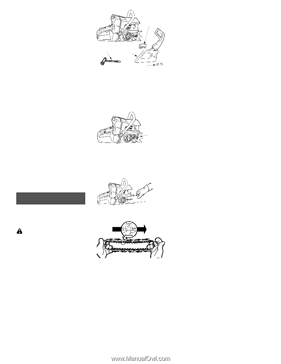
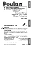
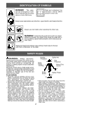
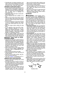
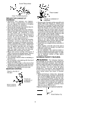
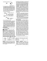
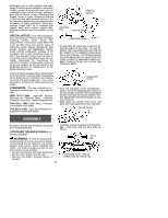
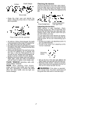
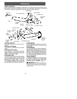
Prolonged use in cold weather has been linked to blood vessel damage in otherwise healthy people. If symptoms occur such as numbness, pain, loss of strength, change in skin color or texture, or loss of feeling in the fingers, hands, or joints, discontinue the use of this tool and seek medical attention. An anti-vibration system does not guarantee the avoidance of these problems. Users who operate power tools on a continual and regular basis must monitor closely their physical condition and the condition of this tool. SPECIAL NOTICE: Your saw is equipped with a temperature limiting muffler and spark arresting screen which meets the requirements of California Codes 4442 and 4443. All U.S. forest land and the states of California, Idaho, Maine, Minnesota, New Jersey, Oregon, and Washington require many internal combustion engines to be equipped with a spark arresting screen by law. If you operate a chain saw in a state or locale where such regulations exist, you are legally responsible for maintaining the operating condition of these parts. Failure to do so is a violation of the law. Refer to the SERVICE section for maintenance of the spark arresting screen. Failure to follow all Safety Rules and Precautions can result in serious injury. If situations occur which are not covered in this manual, use care and good judgement. If you need assistance, contact your authorized service dealer. STANDARDS: This saw is listed by Underwriter's Laboratories, Inc., in accordance with: ANSI B175.1-2000 American National Standard for Powered Tools -- Gasoline Powered Chain Saw -- Safety Requirements CSA Z62.1--1995 Chain Saws -- Occupational Health and Safety CSA Z62.3--1996 Chain Saw Kickback Occupational Health and Safety Shipping Spacer Assembly Tool Chain Brake Chain Brake Nuts S An adjusting pin and screw is used to ad- just the tension of the chain. It is very important when assembling the bar, that the pin located on the adjusting screw aligns into a hole in the bar. Turning the screw will move the adjustment pin up and down the screw. Locate this adjustment before you begin mounting the bar onto the saw. See illustration below. Adjustment Screw S Turn the adjusting screw counterclockwise to move the adjusting pin almost as far as it will go to the rear. This should allow the pin to be near the correct position. Further adjustment may be necessary as you mount the bar. S Slide guide bar behind clutch drum until guide bar stops agaist clutch drum sprocket. Mount the bar ASSEMBLY Protective gloves (not provided) should be worn during assembly. ATTACHING THE BAR & CHAIN (If not already attached) WARNING: If received assembled, repeat all steps to ensure your saw is properly assembled and all fasteners are secure. Always wear gloves when handling the chain. The chain is sharp and can cut you even when it is not moving! S Loosen and remove the chain brake nuts and the chain brake from the saw. S Remove the plastic shipping spacer (if present). S Carefully remove the chain from the package. Hold chain with the drive links as shown. Tip of Bar CUTTERS MUST FACE IN DIIRECTION OF ROTATION 6
-
 1
1 -
 2
2 -
 3
3 -
 4
4 -
 5
5 -
 6
6 -
 7
7 -
 8
8 -
 9
9 -
 10
10 -
 11
11 -
 12
12 -
13
-
14
-
15
-
16
-
17
 |
 |