Poulan 4400-4900-5400 Parts List - Page 2
/85, Chain, Models
 |
View all Poulan 4400-4900-5400 manuals
Add to My Manuals
Save this manual to your list of manuals |
Page 2 highlights
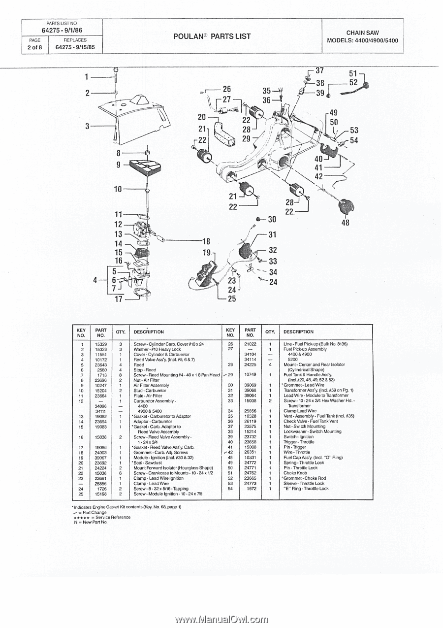
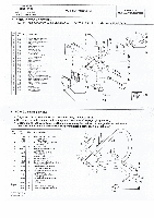
PARTS LIST NO 64275 - 9/1/86 PAGE 2 of 8 REPLACES 64275 - 9/15/85 1 2 3 8 9 10 11- v1 12 13 14 15 16 5 4 6J 17 POULAN® PARTS LIST CHAIN SAW MODELS: 4400/4900/5400 26 35 -1- 1 36 -I 20 22 211 28 22 29 - " N 21 22 _I 28 22. 4- 30 31 18 19 .f--32 33 yet ")\ 34 / 23 24 24 -25 37 51 38 f-- 52 39 49 50 53 54 40 I 41 48 •-• CV CI .1 tr, CD NCO C -0v---N KEY NO. PART NO. 15329 15328 11551 10172 23643 2580 1713 23696 10247 15204 23664 - 34096 34111 19082 23654 19083 15038 19086 24003 39067 23692 24224 15036 23661 25856 1726 15198 OTY. DESCRIPTION KEY Na 3 Screw - Cylinder Carb. Cover #10 x 24 26 3 Washer - #10 Heavy Lock 27 1 Cover -Cylinder & Carburetor 1 Reed Valve Ass'y. (Incl. #5, 6 & 7) 4 Reed 28 4 Stop -Reed 8 Screw- Reed Mounting #4 - 40 x 1 8 Pan Head .-- 29 2 Nut - Air Filter 1 Air Filter Assembly 30 2 Stud -Carburetor 31 1 Plate -Air Filter 32 1 Carburetor Assembly - 33 - 4400 - 4900 & 5400 34 1 'Gasket - Carburetor to Adaptor 35 1 Adaptor -Carburetor 36 1 'Gasket • Carb. Adaptor to 37 Rood Valve Assembly 38 2 Screw- Reed Valve Assembly • 39 1 - 24 x 3/4 40 1 'Gasket - Reed Valve Ass'y. Garb. 41 1 Grommet - Carb. Adj. Screws r42 1 Module - Ignition (Incl. #30 & 32) 48 1 'Seal - Sawdust 49 2 Mount Forward Isolator (Hourglass Shape) 50 6 Screw -Crankcase to Mounts - 10 - 24 x1/2 51 1 Clamp - Load Wire Ignition 52 1 Clamp -Load Wire 53 2 Screw - 8 - 32 x 5/16 • Tapping 54 2 Screw - Modulo Ignition • 10 - 24 x 7/8 PART NO. 21022 - 34104 34114 24225 10749 39069 39068 39064 15038 25856 10528 26119 23575 15214 23732 23658 15008 26351 10:(31 24772 24771 24762 23665 24773 1672 OTY. DESCRIPTION 1 Line - Fuel Pick-up (Bulk No. 8136) 1 Fuel Pick-up Assembly - 4400 & 4900 - 5200 4 Mount - Center and Rear Isolator (Cylindrical Shape) 1 Fuel Tank & Handle Ass'y. (Incl.#20, 48, 49, 52 & 53) 1 'Grommet - Lead Wire 1 Transformer Ass'y. (Incl. #59 on Pg. 1) 1 Lead Wire- Module to Transformer 2 Screw - 10 - 24 x 3/4 Hex Washer Hd. - Transformer 1 Clamp Lead Wire 1 Vent - Assembly - Fuel Tank (Incl. #35) 1 Chock Valve - Fuel Tank Vent 1 Nut - Switch Mounting 1 Lockwasher - Switch Mounting 1 Switch - Ignition 1 Trigger -Throttle 1 Pin - Trigger 1 Wire - Throttle 1 Fuel Cap Ass'y. (Incl. "0" Ring) 1 Spring -Throttle Lock 1 Pin -Throttle Lock 1 Choke Knob 1 'Grommet -Choke Rod 1 Sleeve - Throttle Lock 1 "E" Ring - Throttle Lock VI 'QV, CD r. co c. 8 c.; N Inn Ca Indicates Engine Gasket Kit contents (Koy. No. 68, page 1) = Part Change ***** = Service Reference N = Now Part No.
-
 1
1 -
 2
2 -
 3
3 -
 4
4 -
 5
5 -
 6
6 -
 7
7 -
 8
8
 |
 |