Poulan BP400 User Manual - Page 3
Assembly - parts
 |
View all Poulan BP400 manuals
Add to My Manuals
Save this manual to your list of manuals |
Page 3 highlights
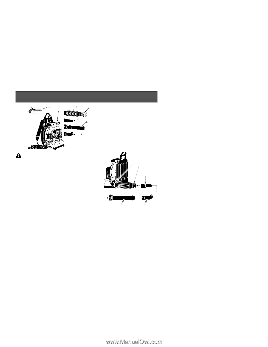
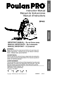
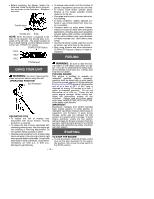
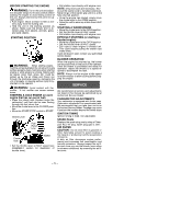
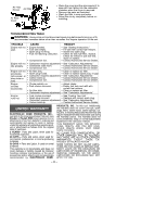
may void your warranty and cause damage to your unit. D Empty fuel tank before storing the unit. Use up fuel left in carburetor by starting engine and letting it run until it stops. D Do not use any accessory or attachment other than those recommended by manufacturer for use with your unit. D Do not store the unit or fuel in a closed area where fuel vapors can reach sparks or an open flame from hot water heaters, electric motors or switches, furnaces, etc. D Store in a dry area out of reach of children. SPECIAL NOTICE: Your blower is equipped with a temperature limiting muffler and spark arresting screen which meets the requirements of California Codes 4442 and 4443. All U.S. forest land and the states of California, Idaho, Maine, Minnesota, New Jersey, Oregon, and Washington require by law that many internal combustion engines be equipped with a spark arrestor screen. If you operate a blower in a state or locale where such regulations exist, you are legally responsible for maintaining the operating condition of these parts. Failure to do so is a violation of the law. SPECIAL NOTICE: Exposure to vibrations through prolonged use of gasoline powered hand tools could cause blood vessel or nerve damage in the fingers, hands, and joints of people prone to circulation disorders or abnormal swelling. Prolonged use in cold weather has been linked to blood vessel damage in otherwise healthy people. If symptoms occur such as numbness, pain, loss of strength, change in skin color or texture, or loss of feeling in the fingers, hands, or joints, discontinue the use of this tool and seek medical attention. An antivibration system does not guarantee the avoidance of these problems. Users who operate power tools on a continual and regular basis must monitor closely their physical condition and the condition of this tool. ASSEMBLY CARTON CONTENTS 1. Engine Assembly 2. Hose Clamp with Screw 3. Flexible Tube 4. Base Tube 5. Middle Tube 6. Nozzle 7. Assembly Tool WARNING: If you receive your unit assembled, check each step to insure your unit is properly assembled and all fasteners are secure. Follow all safety information in the manual and on the unit. D Locate and identify all components. D Slip one hose clamp onto each end of the flexible tube. D Install the flexible tube onto the output tube on the engine. D Connect the base tube to the flexible tube and securely tighten both hose clamp screws. D Assemble the middle tube and nozzle, then connect them to the base tube. Output Tube Flexible Tube Hose Clamps Base Tube Middle Tube Nozzle -- 3 --
-
 1
1 -
 2
2 -
 3
3 -
 4
4 -
 5
5 -
 6
6 -
 7
7
 |
 |