Poulan CHDR500D User Manual - Page 17
Remove, Guard, Replace, Ground, Drive, Adjustment
 |
View all Poulan CHDR500D manuals
Add to My Manuals
Save this manual to your list of manuals |
Page 17 highlights
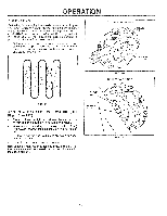
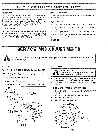
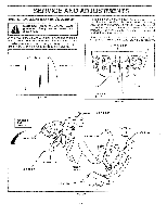
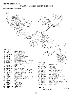
SERVICE AND ADJUSTMENTS TO REMOVE BELT GUARD (See Fig. 27) NOTE: For ease of removal, remove hairpin clip and clevis pin from left wheel. Pull wheel out from tiller about 1 inch (2.5 cm). • Remove screws from side of belt guard. • Remove hex nut and washer from bottom of belt guard (located behind wheel). • Pull belt guard out and away from unit. • Replace belt guard by reversing above procedure. BELT GUARD -') SCREW HEX NUT AND WASHER (LOCATED BEHIND TIRE) o.=--,, A .= .==„ SCREW HAIRPIN CLIP AND CLEVIS PIN FIG. 27 TO REPLACE GROUND DRIVE BELT (See Figs. 27 and 28) • Remove belt guard as described in "TO REMOVE BELT GUARD". • Remove old belt by slipping off engine pulley first then remove from transmission pulley. • Place new belt in groove of transmission pulley and into engine pulley. BELT MUST BE IN GROOVE ON TOP OF IDLER PULLEY. NOTE POSITION OF BELT TO GUIDES. • Check belt adjustment as described below. • Replace belt guard. • Reposition wheel and replace clevis pin and hairpin clip. GROUND DRIVE BELT ADJUSTMENT (See Fig. 28) For proper belt tension, the extension spring should have about 5/8 inch (16 mm) stretch when drive control bar is in "ENGAGED" position. This tension can be attained as follows: • Loosen cable clip screw securing the drive control cable. • Slide cable forward for less tension and rearward for more tension until about 5/8 inch (16 mm) stretch is obtained while the drive control bar is engaged. • Tighten cable clip screw securely. ENGINE PULLEY BELT GUIDE "B" di* 0' CABLE CLIP SCREW DRIVE CONTROL CABLE LESS O TENSION IDLER PULLEY TRANSMISSION PULLEY FIG. 28 17 EXTENSION SPRING 5/8" MORE TENSION
-
 1
1 -
2
-
3
-
4
-
5
-
6
-
7
-
8
-
9
-
10
-
11
-
 12
12 -
 13
13 -
 14
14 -
 15
15 -
 16
16 -
 17
17 -
 18
18 -
 19
19 -
 20
20 -
 21
21 -
 22
22 -
23
-
24
-
25
-
26
-
27
-
28
 |
 |
