Poulan GTT342 User Manual - Page 5
Assembly - bagger
 |
View all Poulan GTT342 manuals
Add to My Manuals
Save this manual to your list of manuals |
Page 5 highlights
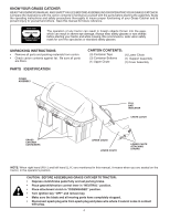
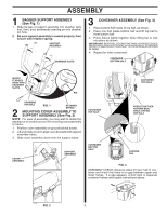
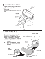
ASSEMBLY 02051 02051 1 BAGGER SUPPORT ASSEMBLY (See Fig. 1) 1. Slide flanges of support assembly into drawbar slots first, then, pivot backwards inserting pin into drawbar pin hole. 2. Be sure support assembly is seated properly, then secure with retainer spring. SUPPORT ASSEMBLY DRAWBAR SLOTS 3 CONTAINER ASSEMBLY (See Fig. 3) 1. Place bottom half inside of top half, as shown. 2. Place one foot inside bottom half and lift top half to meet bottom half. 3. Press halves tightly together while lifting top to lock into place as shown. IMPORTANT: BEFORE LOCKING THE TABS, HOOKED EDGES ON BOTH HALVES MUST OVERLAPTO FORM SEAL AS SHOWN IN INSET. 4. Repeat for other containers. CONTAINER BOTTOM HALF INSERT FLANGES FIRST INTO DRAWBAR SLOTS 02051 02543 PIN DRAWBAR PIN HOLE FIG. 1 RETAINER SPRING 2 MOUNTING COVER ASSEMBLY TO SUPPORT ASSEMBLY (See Fig. 2) NOTE: For ease of assembly, you may wish to obtain the assistance of another person for mounting coverassembly to tractor. 1. Position cover assembly on ground behind tractor. 2. Lift and rotate cover to align cover brackets with support assembly tubes. 3. Slide cover assembly down onto the support tubes. COVER ASSEMBLY SUPPORT ASSEMBLY CONTAINER TOP HALF 02739 02089 CONTAINER TOP HALF PRESS TOGETHER TO FORM SEAL WHILE LIFTING TOP HALF CONTAINER BOTTOM HALF LOCKING TAB FIG. 3 ASSEMBLY CHECK: Squeeze sides of lower half of container and check that there is no gap between upper and lower halves. If a gap appears, unlock tabs to separate container halves and repeat instructions above. 02097 W DrenlndyoitesAlnyds.ouRrRteboepjNepplacelIatcrNcaetoetmGewwemenhaoterwcnoacennrratduacnkidneleeedtsrie.sorricodoraanmttiaoainng.eeCrdih.seUpcsrkoebpoaenglyfraeqreucomme 03024 FIG. 2 5
-
 1
1 -
 2
2 -
 3
3 -
 4
4 -
 5
5 -
 6
6 -
 7
7 -
 8
8 -
 9
9 -
 10
10 -
 11
11
 |
 |
