Poulan HD145H42G User Manual - Page 6
Assembly
 |
View all Poulan HD145H42G manuals
Add to My Manuals
Save this manual to your list of manuals |
Page 6 highlights
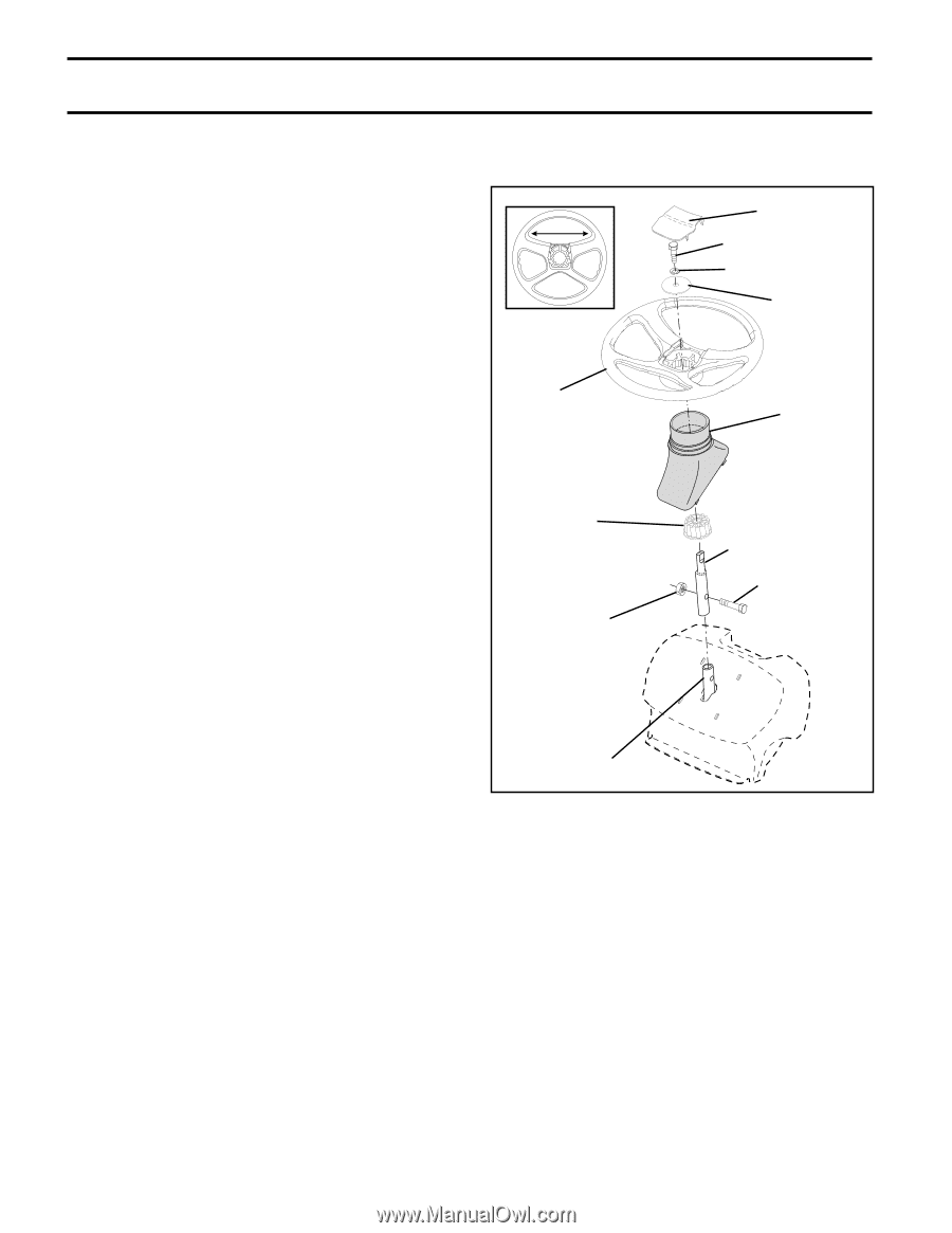
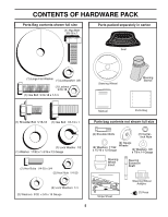
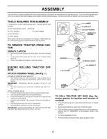
ASSEMBLY Your new tractor has been assembled at the factory with exception of those parts left unassembled for shipping purposes. To ensure safe and proper operation of your tractor all parts and hardware you assemble must be tightened securely. Use the correct tools as necessary to insure proper tightness. TOOLS REQUIRED FOR ASSEMBLY A socket wrench set will make assembly easier. Standard wrench sizes are listed. (1) 3/4" Socket w/drive rachet Utility knife (2) 7/16" wrenches Tire pressure gauge (2) 1/2" wrenches (1) 9/16" wrench When right or left hand is mentioned in this manual, it means when you are in the operating position (seated behind the steering wheel). TO REMOVE TRACTOR FROM CARTON UNPACK CARTON • Remove all accessible loose parts and parts cartons from carton (See page 5). • Cut, from top to bottom, along lines on all four corners of carton, and lay panels flat. • Check for any additional loose parts or cartons and remove. BEFORE ROLLING TRACTOR OFF SKID ATTACH STEERING WHEEL (See Fig. 1) ASSEMBLE EXTENSION SHAFT AND BOOT • Slide extension shaft onto lower steering shaft. Align mounting holes in extension and lower shafts and install 5/16 hex bolt and locknut. Tighten securely. IMPORTANT: TIGHTEN BOLT AND NUT SECURELY TO 18-22 FT. LBS TORQUE. • Place tabs of steering boot over tab slots in dash and push down to se- cure. INSTALL STEERING WHEEL • Position front wheels of the tractor so they are pointing straight forward. • Slide steering wheel adapter onto steering shaft extension. • Position steering wheel so cross bars are horizontal (left to right) and slide inside boot and onto adapter. • Assemble large flat washer, 3/8 lock washer, 3/8 hex bolt and tighten se- curely. • Snap steering wheel insert into center of steering wheel. • Remove protective materials from tractor hood and grill. IMPORTANT: CHECK FOR AND REMOVE ANY STAPLES IN SKID THAT MAY PUNCTURE TIRES WHERE TRACTOR IS TO ROLL OFF SKID. STEERING WHEEL ADAPTER 5/16 LOCKNUT INSERT 3/8 HEX BOLT 3/8 LOCK WASHER LARGE FLAT WASHER STEERING BOOT EXTENSION SHAFT 5/16 HEX BOLT LOWER STEERING SHAFT FIG. 1 TO ROLL TRACTOR OFF SKID (See Operation section for location and function of controls) • Press lift lever plunger and raise attachment lift lever to its highest position. • Release parking brake by depressing clutch/brake pedal. • Place freewheel control in freewheeling position to disengage transmission (See "TO TRANSPORT" in the Operation section of this manual). • Roll tractor backwards off skid. • Remove banding holding discharge guard up against tractor. 6
-
 1
1 -
 2
2 -
 3
3 -
 4
4 -
 5
5 -
 6
6 -
 7
7 -
 8
8 -
 9
9 -
 10
10 -
 11
11 -
 12
12 -
13
-
14
-
15
-
16
-
17
-
18
-
19
-
20
-
21
-
22
-
23
-
24
-
25
-
26
-
27
-
28
-
29
-
30
-
31
-
32
-
33
-
34
-
35
-
36
-
37
-
38
-
39
-
40
-
41
-
42
-
43
-
44
-
45
-
46
-
47
-
48
-
49
-
50
-
51
 |
 |